Slave to the Game
Online Gaming Community
ALL WORLD WARS
SERVICE AND DESCRIPTION OF GATLING GUNS, 1878
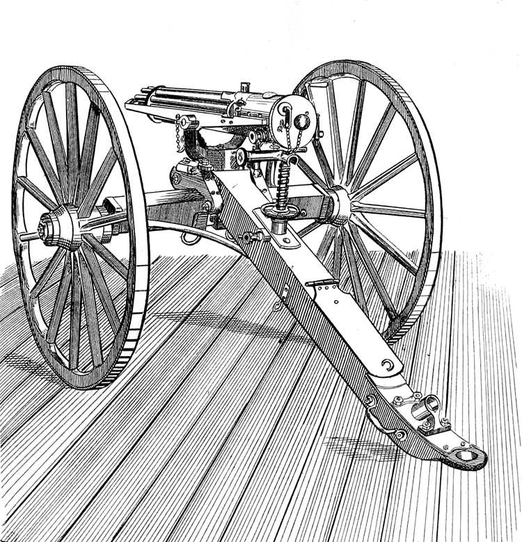
Fig.1. Gatling gun
Department of Tactics and Practical Instruction
United States Artillery School
Fort Monroe, Virginia. 1878.
SERVICE AND DESCRIPTION OF GATLING GUNS.
Headquarters Artillery School, U. S. A.,
Fort Monroe, Va.} November 30, 1877.
It having been found expedient to revise Circular No. 3, series of 1874, and the same having received the approval of the General of the Army and Staff of the Artillery School, U. S. A., it is now published, together with other matter which is likewise authorized, for the guidance of officers of this command. By order of Colonel Getty:
CONSTANTINE CHASE, First Lieutenant Third Artillery, Adjutant and Secretary of Staff,
New York, December 20, 1873.
GENERAL
The board met pursuant to the call of the president, all the members being present, and proceeded to a discussion of the results of the trials, and the preparation of their report. Having agreed upon the recommendations to be made, the form of report, and the character of the drawings and diagrams of targets to accompany the same, the board adjourned to meet agaiu at the call of the president, should another meeting be deemed necessary, otherwise the report to be sent by the president to the other members for their signatures.
No subsequent meeting was held.
The Gatlitig gun, shown on its carriage in Fig. 1, may be described as consisting of a number of very simple breech-loading rifled barrels grouped around and revolving about a common axis, with which they lie parallel. These component barrels are loaded and fired while revolving, the empty cartridge-shells being ejected in continuous succession. Each barrel is tired only once in a revolution, but as many successive shots are delivered during that time as there are different barrels, so that the ten-barrel Gatling gun fires ten times in one revolution of the group of barrels. The action of each p art is therefore quite deliberate, while collectively the discharges are frequent. The working of the gun is simple. One man places one end of a feed-case full of cartridges into a hopper at the top of the gun, while another man tarns a crank by which the gun is revolved. As soon as the supply of cartridges in one feed-case is exhausted, another case may bo substituted without interrupting the revolution or the succession of discharges. The usual number of barrels composing the gun is ten. The mechanism by which the described results are effected is simple, and can be readily understood from the following description and the accompanying plates.
The ten barrels are grouped around a central shaft, and parallel thereto. The bore of each barrel extends through from end to end, and the breech is chambered to receive a flanged "center-fire" metallic-case cartridge. The breech ends of all the barrels are firmly screwed into a disk or rear barrel-plate, which is fastened to the shaft, while the muzzles pass through another similar disk, called front barrel-plate, ou the same shaft. The shaft is considerably longer than the barrels, and projects beyond tbe muzzles, while it extends backward for some distance behind the breeches of the barrels. Directly behind the open barrels a hollow cylinder of metal, called a carrier -"block, is fastened to the shaft, and in the exterior surface of this carrier-block ten semi-cylindrical channels are cut, which form trough-like extensions of the cartridge-chambers of the barrels to the rear, aud are designed to receive and guide the cartridges while they are being thrust into the barrels, and to guide the empty cases while they are being withdrawn. Behind the carrier-block the shaft carries another cylinder, called the lock-cylinder, in whose surface ten guide-grooves are formed, which are in line with the barrels, and in which slide ten long breech-plugs or locks, called lock-tubes or plungers, by which the cartridges are thrust into the barrels, aud which close the barrels and resist the reaction of the charges when they are fired. This cylinder is called the lock-cylinder because each plug or lock contains a spiral main-spring acting on a firing-pin or hammer, by which the charge is fired, so that the plug performs all the functions of a gun-lock, as well as of a breech-plug. The shaft to which the group of barrels and. both the carrier-block and the lock-cylinder are rigidly attached is free to turn on its axis, the frout end being journaled in the front part of the frame and the rear end in a diaphragm in the brecch-ca&ing. The breech-casing extends to th& rear far enough to contain not only the diaphragm through which the main shaft is-journaled, but also to form in the rear of the diaphragm a cover for the gearing by which the shaft is revolved. This mechanism or gearing consists simply of a toothed wheel fastened to the shaft and worked by an endless screw on a small axle which passes transversely through the case at right angles to the shaft, and is furnished outside the case with a hand-crank. A cascabel-plate closes the end of the case. Each breech-plug or lock carries a hooked extractor, which snaps over and engages the cartridge-llange when the plug is pushed forward, but which, when the plug rotreats, withdraws and ejects the empty case. The cartridge carrier-blok is covered above the frame by a semi-cylindrical shell, which is provided at the top with an opening of suitable size and shape to permit a single cartridge to fall through it into one of the channols of the carrier-block, which it overlies. There is a suitable trough extending upward from this opening aud forming a hopper, in which a straight feed-ease can be placed in a vertical position, containing a number of cartridges lying lengthwise across the case, one above another. Beneath the carrier-block everything is open, so that the cartridges or shells which are withdrawn by the extracting-hooks from the barrels fall to the ground. Within the cylindrical breech-case attached to the frame a heavy ring not quite the length of the lock-cylinder is iastened to tbe case and diaphragm, which nearly fills the space between the inside of the case and the cylinder. Portions of the inside of this ring are so cut away as to leave a truncated, wedge-shaped, annular or spiral cam projecting from the inner surface of the ring, having two helicoidal edges inclined to each other and united by a short, flat plane. Against these edges tbe rear ends of the locks or breech-plugs continually bear, there being room enough for the locks to lie loosely within the parts of the ring which are cut away. The apex of the wedge-shape cam points to the barrels. Each lock is held back against the cam by a lug or born projecting laterally from the end of the lock and entering a grove formed at the base of the cam, in the thin part of the ring.
The shape and position of the cam and grooves may be better understood by reference to the diagram, Fig.2, which shows the cam-ring as it would appear if cut open and spread out flat, the lines A and C being the development of the edges of the helicoidal cam surfaces, B that of the plane surface connecting these, and a and c the grooves for holding and drawing back the locks. The tea locks are shown in their relative positions abutting against the cam surfaces, six of them being shown in section.
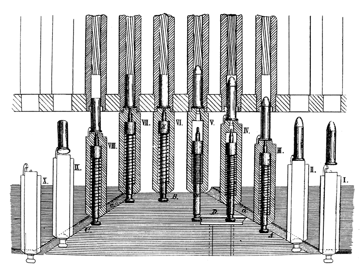
Fig.2. Gatling gun, Calibre 0.42 inch
Development of the spiral cam and firing mechanism
Showing also the action of the locks relatively to the barrels
It will be seen tbat the points of the firing-pins or lock-hammers, H, protrude beyond the front of the locks, while the spindles project from the rear, where they are fashioned into knobs by which the hammers are drawn backward and cocked while passing through the groove in the rib, D.
The diagram shows that the distance of the apex, B, of the cam from the ends of the barrels is such that the breech-plugs or locks exactly fill the space, so that each plug there forms an abutment which closes the breech of its barrel and abuts against the apex of the cam, which serves to resist the recoil of the plug when the charge is fired. It will be remembered that the locks are guided in grooves formed in the lock-cylinder and therefore cannot deviate from their alignment with the barrels. The lock-cylinder and the cartridge carrier-block could not be shown in the diagram, because if they were spread out as the locks are they would cover them and hide them from view. From what has before been explained it will be understood that the ten barrels, the cartridge carrier-block, and the lock-cylinder carrying its ten locks, all shown together in Fig 3, will, by turning the crank, revolve together about the axis of the central shaft, the lock-cylinder revolving within the stationary case and cam-ring, and the cartridge carrier-block revolving beneath the half-cylindrical shell which carries the hopper. Fig. 4 shows the frame which encases the gun, with, the trunnions, breech-casing, and hopper for feeding the cartridges. The cartridges will, as the carrier-block channels come successively under the hopper, drop into the channels in front of the locks and be kept in place by the hopper-shell. The revolution of the lock-cylinder carries the locks around with it, and causes them to receive a longitudinal reciprocal motion by their ends sliding along the inclined surfaces of the stationary cam. Each lock, theu, one after the other, is pushed forward toward its barrel. As the revolution of the parts keeps the locks in contact with the advancing side of the cam, each lock in succession closes its barrel, and its longitudiual motion ceases, while it passes the flat surface of the cam, and then each slides backward from its barrel when constrained to move along the retreating side of the cam by the corresponding cam-groove, and so on, «acb lock repeating these movements at each successive revolution of the shaft.
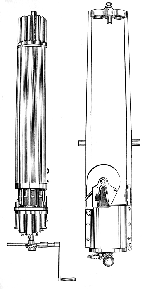
Fig.3, 4. Gatling gun and frame
The position of the cam relatively to the cartridge-hopper is such that each lock is <lrawn backward to its full extent when it passes the hopper, so that the cartridges may fall into the carrier in front of the locks. The explosion of each cartridge takes place as its proper lock passes over the flat apex of the cam which resists the recoil.
The hammer is cocked by the knob or head at its rear end coming into contact with a flat rib located inside of the cam, as shown on the diagram at D. This rib restrains the hammer from moving forward, while the forward movement of the body of the lock continues; the spiral mainspring is compressed until the revolution carries the hammer-knob beyond the end of the cocking-rib, when the hammer will spring forward and strike with its point the center of the cartridge-head and explode the charge. The point in the revolution at which the barrels are discharged is below and at one side oi the axis. The diagram shows the ten locks each in a different part of its cycle of action. At I the cartridge has just dropped in front of the lock, at II it has been pushedt forward somewhat, at III the point of the cartridge has entered the barrel, at IV it is pushed nearly home, and the head of the hammer is retained by the cocking-rib, II, the mainspring being partly compressed. At V the lock has reached the flat part ot rue cam, the cartridge is pushed quite home, and the mainspring has been fully compressed by the retention of the hammer by the cocking-rib, the end of which is just reach by the hammer, which is about being released. At VI the hammer having been released has sprung forward and exploded the cartridge, the end of the lock or breech-plug being firmly braced against the flat surface, B, of the cam. At VII the lock has commenced ro retreat, and at VIII it has partially withdrawn the empty cartridge-shell from tne gun. At IX it has completely extracted the shell, which is falling away from the gun. At X the lock is fully drawn back and is about to pass again into its first position. Thus is will be seen that in the ten-barrel gun one revolution of the barrels corresponds to one revolution of the locks, and delivers ten shots, a process which is repeated contineously so long as the crank is turned and tho cartridges supplied. The gun can be unloaded of any cartridges not fired by removing tho feed-case, opening the hopper, and reversing the motion of the crank. The locks are made interchangeable and are strong and d urable, but should they get out of order the gun is so constructed that any one or all of them can be, in a few moments, taken out and others inserted in their places, and so the gun can he kept in perfect working order at all times on the field of battle. In the new model tbe mechanism of the locks has been greatly strengthened, as well as otherwise improved. and there are means provided for their insertion and removal without taking off the cascabel-plate. These means consist of the perforation of the covering and back diaphragm in the outer casing, and by the closure of the apertures through both these plates by a single removable plug, as shown above the knob of the cascabel in Fig. I.
This is a very valuable improvement, inasmuch as tbe repairing or inspection. of the locks is thereby greatly facilitated. The absence of one or more locks does not affect the working of the gun except to diminish the intensity of fire iu proportion to the number of locks removed. For each lock removed, however, oue uuexplodecl cartridge falls to the ground at each revolution of the gun. The gun is encased in a frame which has trunnions, and is mounted iu the ordinary way, like a field-piece. The screw for elevating and depressing the breech works in a nut attached to the trail of the carriage iu the usual way. An automatic traversing apparatus is applied, by which a limited angular movement in a horizontal plane may be given to the gun, as follows: A cylinder having a cam-groove in its periphery is applied to the crank-axle, and the end of a cylindrical pin enters this groove. The cylindrical pin is attached to an arm which is connected to the elevating-screw; when the crank is turned the cam-groove travels back and forth on the cylindrical pin, swinging the gun from side to side through a sector of three degrees. The pin may be thrown out of gear with the cylinder and the guu be fired without swinging. The sector, covered automatically by the oscillator, may be changed about rive degrees on each side without moving the trail or suspending the firing. The cases which, contain the cartridges, and which are applied to the hopper when it is desired to feed the gun, are long narrow boxes of sheet-tin open only at the lower ends. The cross-section ot the case is trapezoidal, the edge next to which tbe beads lie being much wider than the cartridge-beads, while that which receives the points of tbe balls is of the width of the ball. This form enables all the cartridges in the case to assume a horizontal position, because the heads of tbe contiguous cartridges have room to roll over slightly, so as to lie partly alongside of. each other, while the ball-ends are kept vertically over each other. For drawing of feed-case see Fig. 5. The supply of cartridges to the gun may also be made by what is called the "feed-drum". The straight feed-casss each coutain forty cartridges. The feed-drum (used only with the smaller calibers) contains sixteen radial sectious grouped vertically about the axis of the drum, each section holding twenty cartridges, or three huudred and twenty cartridges to each drum, The number of sections in the drum aud the number of cartridges iu each section maybe varied. The drum rests vertically over the hopper and feeds the cartridges automatically, from the several sections ia succession. The principal objection to tbe drum consists iu the greater number of cartridges which it exposes to au enemy's fire aud the inferior facilities which it affords for packing and transporting the ammunition. The straight feed-cases are deemed to possess superior advantages, and are recommended for all calibers.
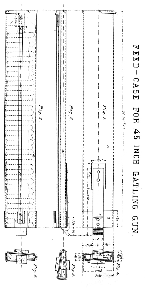
Fig.5. Feed-case for .45 inch Gatling gun
1. Side-view, right
2. Front-view.
3. Side-view, left.
4,5,6 - Bottom view.
a) The case.b) Bottom band. c) Spring-catch. d) Top cap. e&f 40 cartridges. g) Weight.
Weights of the Gatllng 10-barrel guns.
1-inch caliber .......... 650 pounds
0.75-inch and 0.65-inch caliber ..........450
0.55-inch caliber ..........400
0.50-inch, 0.45-inch, and 0.42-inch caliber, with long barrel.......... 200
Same calibers with short barrels .......... 135
Weights of carriages for Gatling 10-barrel guns.
Carriage for 1-inch gun:
Weight of limber and box.......... 790
Weight of gun-carriage ..........1,152
Total ..........1,942
Carriage for 0.42-inch, 0.45-inch, and 0.50-inch guns :
Limber complete ..........387
Gun-carriage complete ..........326
Total ..........713
Weight of empty feed-drum for 0.42-inch-caliber gun, 25 pounds; weight of same filled with 400 cartridges, 60 pounds; weight of empty feed-case for 0.42-inch-caliber gun, 2 pounds 6 ounces ; weight of same filled with 40 cartridges, 5 pounds 15 ounces.
The limber for the 0.42-inch gun will hold 50 cases, or 2,000 cartridges. Aggregate weight of 0.42-inch-caliber gun, gun-carriage, limber, and 2,000 cartridges in feed-cases, 1m 210 pounds. Weight of 5,000 extra 0.42-inch cartridges (1,000 in a box) and 5 packing-boxes, 496 pounds.
12-pounder Napoleon, bronze, Caliber 4,62.)
Weight of ammunition and limber, with implements (pounds) ..........3,895
Weight of ammunition in limber-box when full, (32 rounds)..........497
Weight of tarpaulin ..........36
Weight of gun and limber, with ammunition packed ..........4,428
8-inch siege-howitzer
Weight of gun-carriage and limber ..........3,919
Weight of gun ..........2,614
Total.......... 6,533
There is no limber-box.
41-inch rifle,
Weight of gun-carriage and limber (Pounds) ...........3,641
Weight of gun..........3,450
Total ..........7,091
There is no limber-box.
AMMUNITION FOR GATLING GUNS.
The Gatling guns are designed to be served with ordinary center-fire metallic-case cartridges, in order that the ammunition shall be interchangeable with that for small arms of the same caliber.
For the 1-inch-caliber gun, in addition to the cartridge containing a single solid projectile, a canister-cartridge has been used, containing 15 lead balls, each weighing 141 grains, terminating in front with a one-inch half-round projectile, weighing 1,287 grains.
The total weight of this 1-inch canister-cartridge is 5,190 grains.
The 1-inch solid-ball cartridge is made up as follows:
Projectile ...........3,942 (Grains)
Metallic case ..........1,382
Powder ..........500
Lubricant ..........51
Total ..........5,875
No description of the ammunition for the several calibers is deemed necessary, except that used during the trials.
AMMUNITION USED BY THE BOARD.
With the 0.42-inch Gatling gun.
One trial was made with cartridges containing two balls. In all the other trials but one ball was used, the ammunition being known as the "Berdan center-fire metallic-case cartridge;" the weight of the component parts being as follows :
.
0.42-inch-caliber projectile (Grains) ..........370
Metallic case and lubricant ..........163
Powder, (Hazard's Gatling powder No. 1) ...........77
Total weight of 0.42-inch-caliber cartridge, (see Fig. 6) ..........610
With the 1.00-inch-caliber Gatling gun.
Two kinds of special canister ammunition, devised by the board, were used; one containing 21 round lead balls, and the other 18 cylindrical slugs. The weights ol tuc component parts for each are given below :
Spherical canister for 1.00-inch Gatling gun.
31 lead balls, each 0.45 inch diameter, and weighing 141 grains (Grains) .........2,961
Metallic case ..........1,413
Powder ..........375
Wads and lubricant, about ..........170
Total weight of canister-cartridge with spherical ball, (see Fig. 7).........4,919
Fig. 6-9. Ammunition used with the Gatling 1 inch & 0.42 inch guns
SERVICE OF THE .50 CALIBRE GATLING GUN.
MANUAL OF THE PIECE.
1. The gun detachment. Fire men, including the gunner, are necessary for the service of the piece. With a greater number of cannoneers an exceptionally rapid and continuous fire can be sustained by assigning more men to the duties of exchanging empty for full feed cases, and bringing up ammunition ; but it is advisable not to expose too many men around the gun to the enemy's fire. The detachment is manoeuvred by the same commands and means as for a field gun.
POSTS OF CANNONEERS—PIECE UNLIMBERED.
2. Posts. The gunner at the end of the trail handspike and on its left; Nos. 1 and 2, two feet outside of the wheels and in line with the knob of the cascable, No. 1 on the right, No. 2 on the left, No. 3, 5 yards in rear of No. 2 and covering him ; No. 4 in rear of the limber. All face to the front.
TAKE EQUIPMENTS.
3. The gunner steps to the breech and distributes the cartridge pouches to Nos. 2 and 3; they are worn slung over the left shoulder and under the right arm. The gunner, assisted by No. 1, who steps to the front for that purpose, then removes the canvas cover from the gun, after which No. 1 adjusts the stock-seat; and both resume posts.
SERVICE.
4. Commands. The commands of the instructor are: 1st. Load. 2d. Commence Firing. 3d. Cease Firing. 4th. Secure Piece.
5. Duties of gunner. The duties of the gunner are similar to those prescribed in the Field Artillery Tactics, except that he sits upon the stock-seat in aiming and does not give the command Ready, a signal to No. 3 being sufficient. He removes disabled locks and manipulates the oscillating apparatus. To throw the oscillating apparatus out of gear, the arrow upon the locking block must coincide with the point upon the locking bolt case, and then the handle of the oscillating fork is forced down in its slot and turned to the right.
6.Duties of No1. Load.—No. 1 assumes position at the crank, facing to the front; breaks to the rear with the left foot; releases the crank from the catch; seizes the handle with his right hand, taking care not to turn it until the command Commence Firing is given. No. 1 may, under orders from the gunner, occasionally face to the left while turning the crank.
7. Commence Firing.—No. 1 turns the crank with a moderate uniform motion, avoiding all sudden movements or lateral wrenching. He watches the hopper to see that the cartridges are feeding properly. Cease Firing—He fastens the crank in the catch and returns to his post. If during the firing a cartridge remains in the gun, and it is necessary to use the ejecting rod, No. 1 steps to the front, unkeys it, and, under the direction of the gunner, pushes out the metallic case by forcing it backwards.
8. Duties of No.2. Load.—No. 2 assumes position at the hopper, in rear of the axle, facing to the right, and introduces the feed cases, which be receives from No. 3, successively into the hopper, being careful that the cartridges feed properly, with the projectiles to the front. He lias a full feed case ready in his right hand, and inserts it promptly as he removes the empty one with bis left, so as to preserve a continuous fire. He passes the empty feed cases over his left shoulder to No. 3, or drops them on the ground if No. 3 is not near. Cease Firing.—He leaves the partially used case in the hopper, resumes bis post, and sees that there are five full cases in his pouch.
It is of the first importance that the piece be properly and promptly fed with ammunition, and, when necessary, No. 2 will call Case or Drum to No. 3, so as to insure a continuous discharge.
Duties of No.3. 9. Load.—No. 3 gets five full feed cases from No. 4 and places them in the pouch of No. 2, with open ends to the rear and projectiles down ; he then seizes the end of the trail handspike and gives direction to the piece as indicated by signals from the gunner. When the gunner raises both hands, No. 3 receives five full feed cases from No. 4, and resumes his post. The firing having commenced, No. 3 keeps No. 2 supplied with ammunition by placing full feed cases in the pouch of the latter as soon as it becomes empty ; No. 3 returns to No. 4 the empty feed cases aud receives five fall ones, and so on. If at any time the piece requires a new direction, the gunner commands Point, and No. 3 springs to the end of the trail handspike as above prescribed.
Cease Firing.—No. 3 sees that the empty feed cases are returned to No. 4, and that No. 2 and himself are each supplied with full ones, then resumes his post.
To relieve No. 2 of his constrained position in continuous firing, No. 3 will exchange numbers and duties with him, without interrupting the firing, upon orders from the gunner.
10. Duties of No. 4. Load—No. 4 gets five full feed cases ready for No. 3 and places them in his pouch, open end to the front, projectiles down, and replaces the empty feed cases in the tray when No. 3 returns them. Whenever time is saved by it, No. 3 should take the full feed cases immediately to No. 2, without placing them first in bis own pouch. Cease Firing-No. 4 receives the empty t'ee(\ cases and arranges the trays in the limber so that the top ones contain full feed cases only. The chests hold 20 trays.
When specially rapid and continuous fire is necessary,No. 4 will carry full feed cases directly to No. 2, bringing back empty ones to the limber, and alternating with No. 3 in this duty.
11. Caution. llt should the jnstructor give the command Commence 5 firing without giving the command Load, all that is prescribed under both commands will be executed under the direction of the gunner.
12. Change posts. To change posts with the piece unlimbered, No. 1 faces
about aud changes with No. 4, 4 with 3, 3 with 4J, and 2 with
1; with the piece limbered the even numbers face about and No. 1 changes with 3, 3 with 4, 4 with 2, and 2 with 1.
13. Secure Piece.—The gunner steps to the rear of the breech, lowers the rear sight, aud assisted by No. 1, as prescribed above, places and fastens the cover upon the piece; both then resume posts.
WITH THE FEED DRUM.
Pouches are not worn.
14 Load.—No. 2 takes position at the hopper, facing to the right, receives a full feed drum from No. 3, adjusts it upon the hopper with the assistance of the gunner, throws back the hinged lock from the drum stud, and placing his left thumb on the end of the left hopper-rib and the fore finger upon the neighboring drum stud, he makes the ribs and successive studs coincide so as to keep up a continuous fire. As soon as the cartridges begin to flow from the last compartment No. 2 calls Drum; he removes the empty drum from the hopper, passing it to No. 3, and adjusts the full drum as before.
To assist No. 2 in adjusting the drum. The gunner conies up on the right of the stock.
TO FILL THE FEED DRUM.
15. Invert the drum, unlock it, tarn the bottom plate until the cartridge slot comes directly over a compartment, raise the weight with the left hand and fill in the cartridges regularly, projectiles inwards, letting the weight down slowly until the compartment is full. Repeat the operation until all are filled. Lock the drum before it is placed upright again.
LIMBERING AND UNLIMBERING.
16. Limber Rear, Action Right, &c, the guuner handles the trail handspike and raises the trail ; Nos. 1 and 2 work at the wheels of the carnage ; Nos. 3 and 4 are with the limber, being at the end of the pole when the piece is not horsed. No. 1 adjusts the stock seat upon its prop when the piece is unlimbered aud secures it down to the stock when the piece is Umbered. As soon as the piece is limbered up No. 3 returns all the feed cases or drums to No. 4 to replace in the limber chest, assuring himself that no cartridges are left at the gun.
POST OF THE CANNONEERS, PIECE LIMBERED.
17. Nos. 1 and 2 are opposite and one yard outside the naves of the carriage wheels, Nos. 3 and 4 opposite and one yard outside the naves of the limber wheels, the gunner midway between and on the same Hue with Nos. ^ ana 4, who are on the right of the piece, the odd numbers being on the left.
MOUNTING AND DISMOUNTING THE CANNONEERS.
18. The cannoneers are mounted and dismounted as in the Field Artillery Tactics, except that the gunner and Nos. 1 and 2 mount on the limber of the piece, No. 2 in the middle.
19. Caution. In drilling at the school of the piece, in garrison or camp, it will be well to remove the locks to prevent the unnecessary snapping of the springs, and the cartridges can then be run through the hopper at will, familiarizing the man with the use of the gun without waste of ammunition or injury to the looks.
SERVICE WITH REDUCED NUMBERS.
20. With two men.—The gunner performs his own duties and turns the crauk; No. 1 wears a pouch, points, brings up ammunition, feeds the piece, removes and takes back empty cases.
Three men.—The gunner performs his own duties as with a full detachment and assumes those of Nos. 1 or 2 when either is absent from his proper station ; No. 1 turns the crank and points; No. 2 brings up and serves ammunition and bandies the feed cases.
Four men.—The gunner and Nos. 1 and 2 perform the same duties as with a full detachment; No. 3 points, brings up ammunition, takes back empty feed cases, and has charge of the limber.
| Numbers retained. | Distribution of duties. |
|||
| Gunner | 1 | 2 | 3 | |
| Gunner and 1 | G.,1 | 2, 3, 4 | ||
| Gunner, 1, and 2 | G | 1, 3 | 2, 4 | |
| Gunner, 1, 2, and 3 | G | 1 | 2 | 3, 4 |
NOMENCLATURE OF THE .50 CALIBRE GUN.
21. For instruction, tbe instructor forms the detachment around the piece and points out the nomenclature; the meu should be frequently questioned as well.
IN VIEW.
Socket (of brass for head of
elevating screw).
Guide plate (of socket) attached
to breech.
Locking block (of brass for
locking bolt).
Plug (for removing the locks).
Regulating nut (on oscillatting cam).
Ihumb spring (on regulating nut).
Oscillating cam.
Rear sight.
Rear sight socket.
Crank catch.
Hopper.
Spindle.
Grooves.
Spring catch.
Ejector.
Hinges.
WITHIN THE BREECH CASING.
Cooking knob.
Cooking device.
Worm.
Worm gear.
THE CARRIAGE AND APPENDAGES.
Swivel.
Swivel socket.
Elevating screw nut.
Elevating nut handle.
Elevating screw clamp.
Stock seat, with hinge and prop.
Feed drum.
Drum head.
Drum handle.
Drum cylinder.
Drum studs.
Cartridge weights.
Weight slots.
Partitions.
Compartments.
Spindle hole.
Drag hooks.
Pointing ring.
Pointing socket.
Ejecting rod.
Wiping rod.
Ktod case and key.
Oscillating arm.
Fork.
Fork handle.
Fork case with slot for handle.
Fork spring (spiral).
Fork clamp screw.
Locking bolt.
Bolt case.
Locking lever.
Drum base, with cartridge slot and two ribs, one with hinged lock to fit on drum studs and thus stop the flow of cartridges, and the other indicating where the drum studs should be held during firing.
METHOD OF TAKING THE .50 CALIBRE GUN APART.
1. Remove the locks in the following manner: Turn the breech plug so that the mark on it and the mark on the cascable plate correspond, then turn the crank until one of the marks on the brass barrel flange is brought to agree with the arrow on the hopper, and pull out the plug, which will bring with it a lock; then reinsert the plug; repeat the operation until all the locks are removed.
2. Raise the rear sight to its full height, take off the cascable plate (which is screwed to the breech casting).
3. Remove the crank shaft, fifst taking off the oscillating pcrew and worm which are fastened to itj then remove the worm gear.
4. Remove the cocking device, by taking out the front and rear screws which hold it to the breech casting and frame.
5. Take out the screws which hold the breech casting to the frame.
6. Block up the barrels close to the rear flange; then remove the breech casting.
7. The large rear nut on the shaft in the rear of the lock cylinder, and which serves as a guide for the rear end of the locks, is fastened to its place by a pin and a left-handed screw. To remove this nut the pin must be taken out and the nut turned to the right, then remove the lock cylinder and carrier from the main shaft. The spiral cam need not be taken out of the casting in order to take the gun apart nor ueed the hopper be taken off, but it should be thrown back on its hinge to allow the removal of the breech casting.
METHOD OF ASSEMBLING THE .50 CALIBRE GUN.
1. Put the main shaft to its place through the plates which hold the barrels, and then put to their proper places the carrier lock cylinder and large rear nut. The last should be screwed up tight and have the tapered piu put through the nut and shaft.
2. Place the gun within the frame, and let the front end of the main shaft rest in the bole designed for it in the front frame. Care should be taken to keep the axis of the main shaft in the plane of the top of the frame; when the gun is in this position the breech casting can be shoved over the cylinder, &c, to its proper place. Screw the casting to the frame, putting, in the mean time, the cocking device to its proper place.
3. Put on the gear wheel, replace the crank, shaft, worm,&c; then put on the cascable plate, revolve the crank to
the right, or to the left, until one of the marks on the barrel
flange is brought on a line with the arrow on the hopper,
then insert a lock, which is shoved to its place by the plug;
remove the plug and repeat the operation until all the
locks are inserted iu their places. This gun is mounted on
a special carriage.
SERVICE OF THE 1-INCH GATLING GUN.
MOUNTED ON A FIELD CARRIAGE.
1. The gun detachement, post, &c. The detachment for the service of the piece and the position of the cannoneers, both with the gun limbered and unlimbered, is the same as for a field piece; the detachment is manoeuvred by the same commands and means, with the following modifications:
TAKE EQUIPMENTS.
2. The gunner steps to the breech and distributes the cartridge pouches to Nos. 2, 5, and 7; they are worn slung over the left shoulder and under the right arm.
SERVICE.
3. Ccommands. The commands of the instructor at standing gun drill are: 1st. Load. 2d. Commence Firing. 3d. Cease Firing. 4th. Secure Piece.
4. Duties of the gunner. In addition to exercising a general supervision over the other canuoneerSs the duties of the gunner are as follows: On receiving the command or sigual to Commence Firing, he gives the command Load; takes bold of the handspike at the end with the right hand and at the centre with his left; places his left knee against the left hand, bending over it, the right knee being slightly bent; looks over the top of the piece and gives the direction. He then steps to the breech and adjusts the rear sight at the required elevation; drawing bac< his right foot, bending over his left knee, and sighting through the notch of the rear sight, he seizes the handles of the elevating screw and gives the proper elevation and exact direction. When the piece is loaded and pointed, he stations himself where he can best observe the effects of the shots and commands Commence Firing.
When the instructor, instead of giving the command Commence Firing, gives that of Load, the gunner repeats it and performs the same duties as before, except that he does not command Commence Firing until the instructor orders it. After the command Commence Firing is given, the action is continued by the gunner without command from the instructor until the firing is ordered to cease.
5. Duties of No.1. Load.—No. 1 faces about and places himself rapidly between the piece and the wheel in rear of the axle, facing to
the front, breaks to the rear with the left foot, seizes the crank handle, taking care not to turn it until the cotnmaud Commence Firing is given.
6. Commence Firing.—No. 1 turns the crank with a moderate uniform motion, avoiding all sudden movements or lateral wrenching, and allowing ample time for the cartridges to drop from the feed cases into the carrier. He watches the hopper to see that the cartridges are feeding properly. Cease Firing.—He returns to his post outside the wheel. If during the tiring a cartridge remains in the gun a/id it is necessary to use the ejecting rod, No. 1 steps to tiie front, unkeys it, and, under the direction of the gunner, pushes out the metallic case by forcing it backwards.
7. Duties of No.2. Load.—No. 2 faces to his right and assumes position in front of the axle between the wheel and piece, facing to the rear, and, when No. 4 calls Case, he removes the case in the hopper, puts on its cover, which he has received from No. 5 or 7, and hands the empty cases to those numbers when they come for them. Cease Firing.—He leaves the case in the hopper, if it is not empty, and resumes his post outside the wheel.
8. Duties of no.3. Load.—No. 3 goes to the end of the trail handspike,
seizes it with both hands as soon as the gunner goes to the
elevating screw, and prepares to move it to the right or
left on a signal from the gunner. No. 3 remains at the end of the trail handspike and assists the gunner to point the piece. At Cease Firing he resumes his post outside the wheel.
9. Duties of No.4. Load.—No. 4 stations himself at the hopper in a position similar and opposite to that of No. I, facing to thenght;
he receives the full feed cases from No. 5 or 7 and introduces them into the hopper, with the hole to the right and Projectile to the front; he calls Case as the last cartridge Passes the hole, receives a full feed case with his right hand from No. 5 or 7 and inserts it in the hopper as tne empty case is removed by No. 2, thus keeping a continuous stream of cartridges fed to the gun. Cease Firing.—He resumes his post outside the wheel. Nos. 4 and 2 will exchange duties and numbers when ordered by the gunner
but without interrupting the firing.
10. Duties of No.5. Load.—No. 5 runs to the ammunition chest, receives four full cases from No. 7 or 6, takes them to the piece, and places himself to the right and rear of No. 4, facing to the right. Commence Firing.—He removes the cover from a case and hands it to No. 2, the case to No. 4. This he continues until his pouch is empty, when he makes a signal to No. 7, gets the empty feed cases from No. 2, which he returns to the limber, receives full cases from No. G, and resumes his post, while No. 7 assumes his place and duties beside No. 4. Cease Firing.—He sees that the empty feed cases are returned to No. 6, receives four full feed cases in his pouch, and resumes his post. When the piece is limbered up, he returns all the cases to the limber, which are put away by Nos. 6 and 7, and assures himself that there are no cartridges in the piece.
11. Duties of No. 7. 10. As soon after the command Load as No. 5 is supplied with full cases, No. 7 gets four full cases in his pouch, and upon the signal from No. 5 he assumes his place and duties beside No. 4. As soon as he has passed all of his cases to No. 4 he calls No. 5, gets the empty cases from No. 2, returns them to the limber,and gets full cases in his pouch ready to relieve No. 5. Cease Firing.—Resumes his post.
12. Duties of Nos. 6 and 8. Nos. 6 and 8 attend to the supply of ammunition. The empty feed cases are filled at the limber or caisson,
care being taken to place the projectile to the left. To fill a feed case it should rest on the left fore-arm, inclining downwards, the side containing the hole uppermost, the open end supported in the hollow of the left hand. The first cartridge is introduced (point to the left) and gradually pushed to the bottom of the case by those succeeding it. When not otherwise engaged, the numbers from 5 to 8 inclusive should be employed in filling feed cases. Cease Firing.—The empty feed cases are filled and returned to the limber, No. 6 securing the lid.
With the feed drum the gun can be fired with equal rapidity without clustering men so dangerously about the piece.
13. Change posts. .—(See Par. 155 and 174, Field Artillery Tactics.)
14. Mechanical manoeuveres. When necessity requires it, the Gatling gun may be dismounted and mounted as a field piece, care being observed to place a block of wood to receive the gun frame and to prevent injury to the front sight or barrels. The gun can also be mounted and dismounted with the gyn, and this method must be the habitual one.
15. In drilling at the school of the piece, in garrison, or camp, when cartridges are not u^ed, it will be well to turn the crank backwards, to prevent the unnecessary snapping of the spring.
SERVICE WITH REDUCED NUMBERS.
16. With two mere.—The gunner performs all his own duties and turns the crank; No. 1 wears a pouch, inserts full feed cases into the hopper and removes empty ones, points, brings up ammunition, and takes back empty feed cases.
Three men.—The gunner performs the same duties as with two men; No. 1 points, brings up ammunition, and takes back empty feed cases. No. 2 inserts full feed cases into tbe hopper and removes empty ones. Nos. 1 and 2 wear pouches.
Four men.—The gunner and No. 1 perform their own duties as with a full detachment; No. 2 inserts fall feed cases into the hopper and removes empty ones ; No. 3 points, brings up ammunition, and takes back empty feed cases.
Five men.—The gunner and No. 1 perform the same duties as with a full detachment; No. 2 brings up ammunition and takes back empty feed cases; No. 3 points, ami alternates with No. 2 in carrying feed cases and ammunition; No. 4 wears a pouch, inserts full feed cases into the hopper and removes the empty ones.
Six men.—The guuner and Nos. 1, 2, and 4 perform the same duties as with five men; No. 3 points; No. 5 altercates with No. 2 in carrying ammunition and feed cases.
Seven men.—No. 6 alternates with No. 5 in carrying ammunition and feed cases; the other cannoneers perform the same duties as with a full detachment.
| Numbers retained | Distribution of duties |
||||||
| Gunner | 1 | 2 | 3 | 4 | 5 | 6 | |
| Gunner, 1 | G., 1 | 2,3,4,5,6,7 | |||||
| Gunner, 1, 2 | G., 1 | 3,5,6,7 | 2,4 | ||||
| Gunner, 1, 2, 3 | G. | 1 | 2,4 | 3,5,6,7 | |||
| Gunner, 1, 2, 3, 4 | G. | 1 | 7 | 3,5,6 | 4,2 | ||
| Gunner, 1, 2, 3, 4, 5 | G. | 1 | 7 | 3 | 4,2 | 5,6 | |
| Gunner, 1, 2, 3, 4, 5, 6 | G. | 1 | 2 | 3 | 4 | 5 | 6,7 |
NOMENCLATURE OF THE 1-INCH GUN.
17. For instruction, the instructor forms the detachment around the piece and points out the nomenclature; tne men should be questioned as well.
IN VIEW.
Main shaft (around which the barrels are clustered).
Frout plate (which supports the front of the barrels).
Rear plate (which supports the rear end of the barrels).
Barrels.
Gun frame.
Trunnions.
Gun face.
Front sight.
Rear sight.
Breech casing.
Elevating screw.
Breech-casing screws.
Cascable plate.
Hopper.
Ejector (attached to hopper.)
Cartridge carrier.
Crank.
Elevating screw box.
Elevating screw bed.
Elevating-screw handle.
Wiping rod (brass).
Ejecting rod (iron).
Lock.
Lock tube.
Lock hammer.
Lock spring.
Firing pin.
Extractor.
WITHIN THE BREECH CASING.
Lock cylinder. Rear guide nut. Cocking ring. Cocking ring clamps. Spiral cam.
Diaphragm.
Diaphragm plug.
Gear wheel.
Pinion.
Rear cam screw.
METHOD OF TAKING THE 1-INCH GATLING GUN APART.
1. Block up the frame and barrels.
2. Take off the hopper.
3. Take off the cascable plate.
4. Takeout the steady pin, and then turn the crank downwards; remove the crank shaft in that position.
5. Take out the rear sight, aud then remove the large gear wheel.
6. Take out rear plug in the diaphragm, and then gently revolve the gun until a lock presents itself on a line with the hole in the diaphragm, through which one lock after another may be taken out.
7. Take out the breech casing screws, then remove the casing to the rear. Be careful to have the lock cylinder and gun supported, so as to keep the centre line of the main shaft parallel to the top of the frame, which is necessary to prevent the rear end of the gun from dropping when the casing is removed.
8. The large rear nut, on the main shaft in the rear of the lock cylinder, and which serves as a guide for the rear ends of the locks, is fastened to its place by a pin and a left-handed screw. To remove this cut, the pin must be taken out and the nut turned to the right. Then, remove the lock cylinder and carrier from the main shaft.
The spiral cam need not be taken out of the casiug iu order to take the gun apart.
METHOD OF ASSEMBLING THE 1-INCH GUN.
1. Put the main shaft in its place through the plates which hold the barrels, and then put in their proper places the carrier lock cylinder and large rear nut. The latter should be screwed up tight, and have the taper pin put through the nut and shaft.
2. Place the gun within the frame, and let the front end of the main shaft rest in the hole designed for it in the front of the frame. When the gun is in this position, the cocking riug should be shoved over the lock cylinder aud left for the time loosely around the carrier.
3. Let the breech of the gun be slightly raised, when the breech casing can be shoved over the lock cylinder, &c, to its place, then screw the casing to the frame, putting the cocking ring in its proper place in the mean time. Revolve the guu to the right or left, so that the places for the locks will come on a line with the hole in the diaphragm, through which one lock at a time can be inserted in its proper position; afterward the screw plug should be inserted to close the hole through the diaphragm.
4. Put on the cog wheels, replace the crank shaft, pinion, and steady pin. Put on the rear sight, and screw on the cascable plate and hopper, and the gun is ready to be mounted. This gun is mounted on a 6 pounder field carriage, widened between the cheeks to receive it. The ammunition chests are arranged for twelve trays.
SERVICE OF THE 45 CALIBRE GATLING GUN. MOUNTED ON A CAVALRY CART.
By Captain W. F. Randolph, Fifth Artillery.
1. The gun detachement. Four men, including the gunner, are necessary for the service of the piece; with a greater number of cannoneers a more rapid and continuous fire can be sustained (the additional men refilling feed cases and bringing up ammunition), but it is not advisable to expose more men than are absolutely necessary.
2. Preliminary. The animal being unhitched, the muzzle is pointed in the desired direction by the gunner and Nos. 1 and 2 working, the former at the shafts ami the two latter at the wheels; the shafts and prop are then allowed to rest upon the ground.
POSTS OF CANNONEERS, PIECE UNHITCHED.
3. Posts. The gunner in the rear of the piece, covering it, and at the end of the shaft ; No. 1 two feet outside, and opposite the rear part of the right wheel; No. 2 two feet outside, and opposite the rear part of the left wheel; No. 3 five yards in rear of and covering No. 1, all facing to the front.
4. The gun cover. The cover is removed from the piece by the gunner, The gun cover. assisted in front by No. 1, who folds and places it in the tool box and resumes his post.
5. Commands. The commands of the instructor are: 1st. Load. 2d. Commence Firing. 3d. Cease Firing. 4th. Secure Piece— and are repeated by the gunner.
6.Duties of the gunner. The duties of the gunner are, to direct the piece, observe that the shots are striking at the proper point, see that the supply of ammunition is kept up, throw the oscillating appa ratus in and out of gear, remove disabled locks, see that No.1 is relieved when fatigued by rapid firing, and have general supervision of the gun.
7. The duties of No. 1 are, to fire the gun, see that the cartridges are feeding properly from the case, and use the ejecting rod when necessary, under the direction of the gunner.
8. The duties of No. 2 are, to supply the piece with ammunition, by taking the feed cases from the ammunition chest and inserting them into the hopper, and to see, as far as lies in his power, that the cartridges are feeding properly.
9. Load. —The ganner steps to the rear of the piece throws his right leg over the shaft, reaches forward, turns up the front sight, and adjusts the rear sight for the required distance. He then gives the piece the proper elevation bv means of the elevating screw, correcting the direction with the traversing screw; should any considerable chauge be required, he loosens both clamp screws, and shifts the bed plate, being very careful to refasten the clamp screws as soon as this is accomplished; he then resumes his post.
10. No. 1, as the gunner resumes his post, springs in by a side step to his left close to the shaft, frees the crank from its latch, and seizes the handle with his right hand, being careful not to turn it until the command Commence Firing.
11. No. 2, stepping to his right hand and over the one nearest to him, takes his place between the shafts in rear of the left ammunition chest, opens it, takes a feed case with his left baud, withdraws it from the chest, and seizes it at the middle with the right hand, back of the hand up, turns it until the spring shall be down, the slot to the right, and inserts it into the hopper; he then takes another feed case, seizing it as before, and staDds ready to remove the empty case with his left hand aud insert the full one into the hopper with his right.
12. Commence Firing—The gunner steps to the side from which he can best observe the effect of the shots.
13. No. 1 turns the crank with a moderate uniform motion, taking care not to derange the position of the gun by sudden jerks or lateral wrenching; should any of the shells not be thrown out after firing, or the piece become jammed in any manner, be will at once notify the gunner, who will see that the proper means are taken to remove the obstruction.
14. No. 2, as soon as the feed case is empty, seizes it, and after replacing it by a full one, returns the empty case to the chest, taking care that the spring enters first, aud is on the under side, and then proceeds as before.
15. Ammunition. The ammunition in the left chest being nearly exhausted, No. 2 notifies the gunner, who calls up No. 3, who takes bis post in rear of and opens the right chest, and stands ready to pass the full cases to No. 2 in rear of No. 1. In taking the feed case from the chest, No. 3 seizes it first at the end, afterwards just above the middle, with his left hand, and hands it to No. 2, so that when the latter seizes it, which he does with his right hand at the middle, the spring shall be down and the slot to his right; No. 2 passes the empty case with his left hand to No. 3, who receives it with his right, and places it in the chest.
16. Cease Firing.—No. 1 ceases to turn the crank, No.2. removes the case from the hopper, the gunner steps to the rear of the piece, opens the hopper, and directs No. 1 to slowly reverse the crank, when he removes the cartridges which have not been fired, passing them to No. 2, who restores them to the feed case, and replaces it in the chest, or hands it to No. 3 if the right chest is being used. No. l secures the crank by the latch; and all resume their posts.
17. Secure Piece.—The gunner steps to the rear of the piece as at the command Load,, runs down the elevating screw, turns down the front, lowers the rear sight, and with the assistance of No. 1, who steps to the front for that purpose, places and fastens the canvas cover upon the piece: both then resume their posts.
PRECAUTIONS TO BE OBSERVED.
18. (a.) Never lay the cover upon the ground, as it is liable to pick up sand and dirt, which may derange the working of the parts.
(b.) A partially filled feed case should not be put back into the ammunition chest without being filled up, as the cartridges may become inverted and jam tbe gun.
(c.) If the gun jams, remove the feed case at once, open the hopper reverse the crank until all the cartridges are taken out; this will be found to save time, unless the cause of the jamming is evident and in the immediate vicinity of the hopper.
(d.) See that all the parts are kept well oiled to prevent friction and scouring.
NOMENCLATURE OF THE .45 CALIBRE GUN.
19. For instruction, the instructor forms the detachment around the piece and points out the nomenclature; the men should be frequently questioned as well.
COMPONENTS.
Adjustable screw nut.
Barrels (10).
Breech casing. Breech casing screws (6).
Bashings (10).
Cartridge carrier.
Cartridge shell ejector.
Cartridge shell ejector screws (3).
Cartridge shell extractor block.
Cartridge shell extractor block screws (2).
Cascable plate.
Cocking device.
Crank.
Crank latch.
Crank shaft.
Diaphragm.
Dowel pins.
Extractor hooks (10).
Firing pins (10).
Front cap.
Main shaft.
Oscillating thread nut and washer.
Rear guide nut.
Hear sight.
Rear plate for barrels.
Hear sight screws.
Front plate for barrels.
Front sight.
Front sight screws.
Gas collar.
Gun frame.
Hopper.
Hopper binge.
Hopper hinge pin.
Hopper hinge screws (2).
Hopper latch.
Hopper latch screws.
Lock cylinder.
Lock cylinder screws (2).
Lock extractor.
Lock extractor screws.
Lock extractor sleeve.
Lock extractor sleeve screws (2).
Lock mainsprings (10).
Lock nuts (10).
Lock tubes (10).
Spiral cam.
Spiral cam screws (2).
Trunnions (2),
Washer for front end of mam shaft.
Worm.
Worm gear.
APPENDAGES.
Adjusting screw wrench.
Brass wiping rod.
Clamp for worm gear.
Feed cases, straight (48).
Lock screw-driver.
Pin wrench.
Bear guide nut wrench.
Shell driver.
Small screw-driver.
Screw-driver.
THE CARRIAGE.
Shafts.
Eye bolts and straps (6).
Splinter bar.
Step.
Hounds.
Assembling bolts.
Prop.
Foot board.
Floor.
Bed.
Bed plate.
Clamp screws (2).
Ammunition chests (2).
Obest handles (2).
Lid.
Lid latch (2).
Corner plates.
Angle irons.
Tool bos.
Tool box latch.
Tool box straps and hinges.
Guard plate.
Linchpins (2).
Washers (2).
TO TAKE THE .45 CALIBRE GATLING GUN APART.
1. Remove the locks.
2. Remove the screws and take off the cascable plate.
3. Remove the screw from the end of the crank shaft and take off the oscillating screw, drive out the steady pin, and take out crank shaft, worm, and sleeve.
4. Remove screw from rear end of main shaft and take off worm gear, using clamp for that purpose.
5. Take off brass traversing apparatus, and block up gua under front of rear plates.
6. Take out screws and remove hopper and breech casing.
7. Unscrew screw from lock cylinder, back out steady pin, which holds the rear guide nut, and remove the nut. (The uut works in a left-hand thread.)
8. Take off lock, cylinder, and carrier block.
To remove the barrels singly, staud the cluster muzzles up, and let the rear end of the main shaft strike gently on a block; the shaft and front plate will be forced off, after which the barrels may be unscrewed with a socket wrench.
To take tbe breech casing apart, remove the screws which liold the double cam to the diaphragm and slide it out to the front.
TO ASSEMBLE THE .45 CALIBRE GATLING GUN.
1. Put the breech casing together, screw the barrels into the rear plate, replace the front plate and shaft, insert the front end of the shaft into the socket in the front of the frame, aud rest the front and rear plates upon blocks.
2. Replace the carrier blocks and lock cylinder.
3. Put on the rear guide nut aud put in'steady pin and screw.
4. Put on breech casing and hopper, and replace the screws.
5. Put on the brass traversing apparatus.
6. Replace worm gear.
7. Replace worm and sleeve and insert crank shaft, fastening the ^vorm in its place with the steady pin.
8. Replace oscillating nut and set screw.
9. Replace cascable plate and screws.
10. Replace locks.
In taking the gun apart it will be found much more convenient and expeditious to first remove the cascable plate and then the locks by hand, and in assembling it they can be inserted in the same manner before replacing the cascable plate.
When the lock extractor is used the breech plug is turned horizontally, the crank handle is turned until the mark upon the rear barrel plate and the arrow on the hopper coincide, when the lock is withdrawn.
DESCRIPTION OF THE GATLING GUN MECHANISM.
[From the report of the Board of Officers, 1873.]
The Gatling gun may be described as consisting of a number of very simple breech-loading rifled barrels, grouped around and revolving about a common axis, with which they lie parallel. These component barrels are loaded and fired while revolving, the empty cartridge shells being ejected in continuous succession. Each barrel is fired only once in a revolution, but as many successive shots are delivered during that time as there are different barrels, so that the ten-barrel Gatling gun fires ten times in one revolution of the group of barrels. The action of each part I is therefore quite deliberate, while collectively the discharges are frequent.
The working of the gun is simple. One man places one end of a feed case full of cartridges into a hopper at the top of the gun, while another man turns a crank by which the gun is revolved. As soon as the supply of cartridges in one feed case is exhausted, another case may be substituted without interrupting the revolution or the succession of discharges. The usual number of barrels composing the gun is ten. The I mechanism by which the described results are effected is simple, aud I can be readily understood from the following description:
The ten barrels are grouped around a central shaft, and parallel 1 thereto. The bore of each barrel extends through from end to end, and I the breech is chambered to receive a flanged "centre fire" metallic case 1 cartridge. The breech ends of all the barrels are firmly screwed iuto a I disk or rear barrel plate, which is fastened to the shaft, while the muzzles pass through another similar disk, called front barrel plate, ou the I same shaft. The shaft is considerably longer than the barrels, and projects beyond the muzzles, while it extends backwards for some distance behind the breeches of the barrels. Directly behind the open barrels a hollow cylinder of metal, called a carrier block, is fastened to the shaft, and in the exterior surface of this carrier block ten semi-cylindrical channels are cut, which form trough-like extensions of the cartridge chambers of the barrels to the rear, and are designed to receive and guide the cartridges while they are being thrust into the barrels, and to guide the empty cases while they are being withdrawn. Behind the carrier block the shaft carries another cylinder, called the lock cylinder, in whose surface ten guide grooves are formed, which are in line with the barrels, and in which slide ten long breech plugs or locks, called lock tubes or plungers, by which the cartridges are thrust into the barrels, and which close the barrels and resist the reaction of the charges when they are fired. The cylinder is called the lock cylinder, because each plug or lock contains a spiral mainspring, acting on a firing pin or hammer by which the charge is fired, so that the plug performs all the functions of a gun lock, as well as of a breech plug. The shaft to which the group of barrels and both the carrier block and the lock cylinder are rigidly attached, is free to turn on its axis, the front and being journalled in the front part of the frame, and the rear end in a diaphragm in the breech casing. The breech casing extends to the rear far enough to contain not only the diaphragm through which the main shaft is journailed, but also to form in the rear of the diaphragm a cover for the gearing by which the shaft is revolved. This mechanism or gearing consists simply of a toothed wheel fastened to the shaft, and worked by an endless screw on a small axle, which passes transversely through the case at right angles to the shaft, and is furnished outside the case with a hand crank. A cascable plate closes the end of the case. Bach breech plug or lock carries a hooked extractor, which snaps over and engages the cartridge flange when the plug is pushed forward, but which, when the plug retreats, withdraws and ejects the empty case. The cartridge carrier block is covered above the frame by a semi-cylindrical shell, which is provided at the top with an opening of suitable size and shape to permit a single cartridge to fall through it into one of the channels of the carrier block, which it overlies. There is a suitable trough extending upward from this opening and forming a hopper, in which a straight feed case can be placed iu a vertical position, containing a number of cartridges lying lengthwise across the case, one above another. Beneath the carrier block everything is open, so that the cartridges or shells which are withdrawn by the extracting hooks from the barrels fall to the ground. Within the cylindrical breech case attached to the frame a heavy ring, not quite the length of the lock cylinder, is fastened to the case and diaphragm, which nearly fills the space between the inside of the case and the cylinder. Portions of the inside of this ring are so cut away as to leave a truncated, wedge-shaped, annular or spiral cam projecting from the inner surface of the ring, having two helicoidal edges inclined to each other and united by a short, flat plane. Against these edges the rear ends of the locks or breech plugs continually bear, there being room enough for the locks to lie loosely within the parts of the ring which are cut away. The apex of the wedge-shape cam points to the barrels. Each lock is held back against the cam by a lug or horn, projecting laterally from the end of the lock, and entering a groove formed at the base of the cam, in the thin part of the ring.
The distance of the apex of the cam from the ends of the barrels is such that the breech plugs or locks exactly till the space, so that each plug there forms an abutment, which closes the breech of its barrel and abuts against the apex of the cam, which serves to resist the recoil of the plug when the charge is fired. It will be rememered that the locks-are guided iu grooves formed iu the lock cylinder, and therefore cannot deviate from their alignment with the barrels. From what has before been explained it will be understood that; the ten barrels, the cartridge earner block, and the lock cylinder carrying its ten locks, will, by turning a crank, revolve together about the axis of the central shaft, the lock cylinder revolving within the stationary case and cam ring, and the cartridge carrier block revolving beneath the half cylindrical shell which carries the hopper. The cartridges will, as the carrier block channels come
successively under the hopper, drop into the channels in front of the locks, and be kept in place by the hopper shell. The revolution of the lock cylinder carries the locks around with it, and causes them to receive a longitudinal reciprocal motion, by their ends sliding along the inclined surfaces of the stationary cam. Each lock, then, one after the other is pushed forward toward its barrel. As the revolution of the parts keeps the locks in contact with the advancing side of the cam, each lock in succession closes its barrel, and its longitudinal motion ceases, while it passes the flat surface to the cam, and then each slides backward from its barrel when constrained to move along the retreating side of the cam by the corresponding cam groove, and so on, each lock repeating these movements at each successive revolution of the shaft.
The position of the cam relatively to the cartridge hopper is such that each lock is drawn backward to its full extent when it passes tbe hopper, so that the cartridges may fall into the carrier in front of the locks. The explosion of each cartridge takes place as its proper lock passes over the flat apex of the cam which resists the recoil.
The hammer is cocked by the knob or head at its rear end coming into contact with a flat rib located inside of the cam. This rib restrains the hammer from moving forward, while the forward movement of the body of the lock continues; the spiral mainspring is compressed until the revolution carries the hammer knob beyond the end of the cocking rib, when the hammer will spring forward, and strike with its point the centre of the -cartridge head, and explode the charge. The point in the revolution at which the barrels are discharged is below, and at one side of the axis. Thus it will be seen that, in the ten-barrel gun, one revolution of the barrels corresponds to one revolution of the locks, and delivers ten shots, a process which is repeated continuously, so long as the crank is turned and the cartridges are supplied. The gun can be unloaded of aay cartridges not fired by removing the feed case, opening the hopper, and reversing the motion of the crank. The locks are made interchangeable, and are strong and durable, but should they get out of order the gun is so constructed that any one or all of them can be in a few moments taken out, and others inserted in their places, and so the gun can be kept in perfect working order at all times ou the field of battle. lu the new model, the mechanism of the locks has been greatly strengthened, as well as otherwise improved, and there are means provided for their insertion and removal without taking off thecascable plate. These means consist of the perforation of the covering and hack diaphragm in the outer casing, and by the closure of the apertures through both these plates by a single removable plug.
This is a very valuable improvement, inasmuch as the repairing or inspection of the locks is thereby greatly facilitated. The absence of one or more locks does not affect the working of the gun, except to , diminish the intensity of fire in proportion to the number of locks removed. For each lock removed, however, one unexploded cartridge falls to the ground at each revolution of the gun. The gun is encased in a frame which has trunnions, and is mounted in the ordinary way, like a field piece. The screw for elevating and depressing the breech works in a nut attached to the rail of the carriage in the usual way. An automatic traversing apparatus is applied, by which a limited angular movement in a horizontal plane may be given to the gun, as follows : A cylinder having a cam groove in its periphery is applied to the crank axle, and the end of a cylindrical pin enters this groove. The cylindrical pin is attached to an arm which is connected to the elevating screw; when «ie crank is turned the cam groove travels back and forth on the cylindrical pin, swinging the gun from side to side through a sector of three degrees. The pin may be thrown out of gear with the cylinder, and the gun be fired without swinging. The sector, covered automatically by the oscillator, may be changed about five degrees on each side without moving the trail or suspending the firing. The cases which contain the cartridges, and which are applied to the hopper when it is desired to feed the gun, are long narrow boxes of sheet tin open only at the lower ends. The cross section of the case is trapezoidal, the edge next to which the heads lie being much wider than the cartridge heads, while that which receives the points of the balls is of the width of the ball. This form enables all the cartridges in the case to assume a horizontal position, because the heads of the continuous cartridges have room to roll over slightly, so as to lie partly alongside of each other, while the ball ends are kept vertically over each other.
The cartridge for the Gatling gun is made of No. 18 sheet copper. The canister consists of a case terminated at one extremity by a hemispheroid of lead called the head ; it contains for the 1-inch gun 15 bullets, .48" in diameter. The charge for this gun is f ounce of mortar powder, and 6 grains of fulminate, that for the .50" and .45" guns is 70 grains of musket powder and £ grain of fulminate. The fulminate used is composed of fulminate of mercury, 3 parts; pulverized nitre, 2 parts; glass dust, J part; chlorate of potassa, 2 parts. This is moistened with gum arable water.
The solid shot consists of a case containing the above composition and charge of powder, with an elongated bullet weighing S ounces for the 1-inch, and 450 grains for the .50" and .45" guns. Canister is only used with the 1 inch gun. The cartridges are put up and issued from the arsenals in pasteboard packages, and when required for service enough are opened to fill the tin feed cases carried in the limbers of the pieces. The ammunition chests of the caissons are filled with unbroken packages. For the .45" gun the ammunition is interchangeable with that for the regulation infantry rifle.
The character of the rifling of Gatling guns is uniform groove, making one turn in 72" for the 1-inch gun, one turn in 42" for .50", and one in 22" for the .45" gun. The effective range is contemplated at from 200 to 1,200 yards, or the zone of infantry fire.
1 screw driver, 1 ivrench is furnished with each piece, lgear extractor, 1 pin ivrench and a curved brass casting, with iron screw and brass straps, called an assembling nut, are furnished with every battery of Gatling guns. The canvas cover should always be kept on the gun except when the latter is served, then it is strapped on the. limber chest of the piece.
Principal weights and dimensions of Gatling guns.
| Parts | 1". | .50". | .45". |
| Gun (pounds) | 1,008 | 365 | 144 |
| Gun carriage, without wheels | 645 | 368 | 575 |
| Two wheels | 360 | 175 | 206 |
| Limber body, without wheels | 335 | 190 | ... |
| Two wheels | 360 | 175 | ... |
| Amminution chest, without trays | 165 | 86 | ... |
| Ammunition trays | 47 | 38.5 | ... |
| Ammunition, in cases | 288 | 252 | ... |
| Implements and equipments | 20 | 15 | ... |
| Paulin (12 by 15) | |||
| TOTAL WEIGHT | 3,263 | 1,6999.5 | 925 |
| Feed drum (filled with 400 cartridges) | ... | 66 | ... |
| Feed rum (empty) | ... | 34 | ... |
| Dimensions | |||
| Extreme length of gun (inches) | 68 | 60 | 35.5 |
| Length of barrell | 33 | 32 | 18 |
| Length of breech casing | 21.5 | 16 | 8.5 |
| Distance between trunnion beds | 16 | 10.5 | 8.25 |
| Height of axis of trunnions from ground | 43.1 | 37 | 43 |
| Diameter of wheel | 57 | 45 | 54 |
| Height of drum | ... | 13 | ... |
| Length of feed case | 14.5 | 14.5 | 20 |
| Number of cartridges in each chest in cases | 360 | 1,440 | 960 |