Slave to the Game
Online Gaming Community
ALL WORLD WARS
ICE RAILWAY BRIDGE OVER THE DNIEPER
BY HAUPTMANN LUDWIG SCHMELLER
ICE RAILWAY BRIDGE OVER THE DNIEPER
Ludwig Schmeller, Hauptmann a.D. (Res.)
WITH A FOREWORD BY GENERALOBERST a.D. FRANZ HALDER
INTRODUCTION BY OBERST a.D. WILHELM WILLEMER
FOREWORD by Generaloberst a.D. Franz Halder
Captain Schmeller has presented herein an authentic account concerning the ice bridge across the Dnieper River. I remember that similar reports on the successful construction of ice bridges across the Dnieper that were used for wide-gauge railways were submitted to me in my capacity as Chief of the Army General Staff.
This daring enterprise, which could not be based upon any construction data or experience, was inspired by favorable reports from the local inhabitants concerning their experiences with ice bridges. Boldness was crowned with success even though the Army engineering agencies charged with the construction of bridges hesitated to assume the responsibility for this undertakings.
In the case of small rivers, the construction of crossings for heavy loads by strengthening the frozen surface had become such a general practice during Russian winters that the German troops, partially in cooperation with the indigenous population, often made use of such bridges.
(s) Franz Halder
INTRODUCTION by Oberst a.D. Wilhelm Willemer
Captain Schmeller's report describes an ice railway bridge across the Dnieper River near Kiev constructed for the purpose of supplying the German Sixth Army, which was operating in the area extending from Kharkov to south of Kursk.
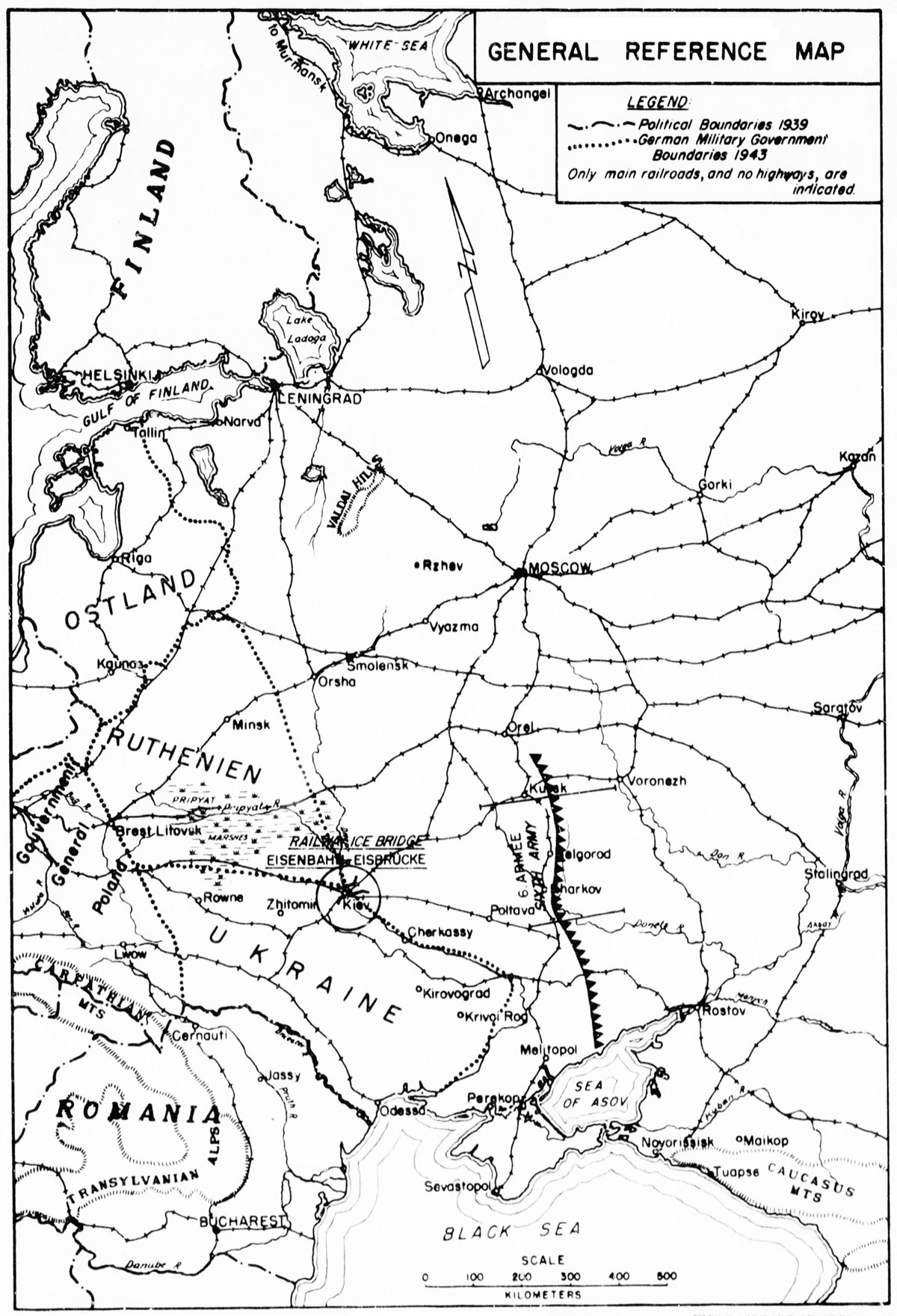
General Reference Map
The supply and railway situation east of the Dnieper was extremely critical during the winter of 1941-42, since the withdrawing Russian troops had destroyed all bridges across the river. At that time only makeshift bridges could be constructed, because many months would be required to build bridges strong enough to resist the pressure of high water. Near Kiev, between Kremenchug and the Pripyat Marshes, there was available only one temporary bridge having a carrying capacity of twenty-two tons. In order to obtain a railway bridge in the brief time available, it was decided to build an ice bridge, as described in this study.
The complete lack of any experience on the part of all competent German agencies was a characteristic of its construction. Hence this ice bridge, built in the surprisingly short time of twelve days, constituted an experiment, and it scored a marked success. It appears therefore worthwhile to record the experiences acquired during its construction, all the more since such an ice bridge can also be used by the heaviest types of tanks.
The author of this account was personally concerned with the building of the bridge in his capacity as Chief of the Construction and Planning Branch of the Transport Command in Kiev. His report is a compilation of his notes supplemented by sketches and photographs which he made on the spot.
CHAPTER 1. THE SITUATION
I. THE RAILWAY SITUATION
In the area east of the Dnieper River the Kiev Transport Command had under its control an insufficient number of locomotives and empty freight cars. A considerable amount of wide-gauge rolling stock, however, was available on the railway lines west of the river between the cities of Lwow - Tarnopol - Shepetovka - Nowograd-Wolinskij - Zhitomir - Fastov - Kiev. Since there was no railway bridge at Kiev, this rolling stock was entirely isolated and could not be utilized for supplying the front. The bridges at Kiev were destroyed to such an extent that their repair would take considerable time. It was expected that the existing makeshift bridge would be pushed away by the drifting ice as soon as a thaw set in. The reconstruction of the railway bridge could not be completed before the middle or even the end of March according to estimates made by the responsible agencies; and the highway bridge, which was under construction, could not be completed before the end of April or the beginning of May at the earliest.
Consequently, there would be a long delay before the Sixth Army could be supplied by rail across the Dnieper from Kiev. Another way had to be found to move the available rolling stock across the Dnieper and to establish a four weeks' reserve of supplies for the Sixth Army.
II. THE ORGANIZATION
The only possible way of accomplishing this task was to move the railway cars across the frozen Dnieper and to deposit an adequate amount of supplies in the area east of Kiev before the river began to thaw, which would occur in from four to six weeks. For this reason it was decided to test the ice covering the Dnieper and to lay rails across the frozen river if such a measure proved feasible. This project was submitted to various agencies but was nowhere granted a hearing nor an adequate understanding.
The Army engineer agencies refused to accept the responsibility for such a venture. Since they were unable to provide the construction data required for an ice bridge and since the statements made by the local inhabitants differed from each other considerably, the Kiev Transport Command was confronted with the task of constructing the ice bridge across the Dnieper on its own responsibility. Sub-section 47 of the Army Construction Office South, in Kiev, was the only agency which supported the plan; after thoroughly examining various suggestions, it decided to undertake the experiment.
The labor problem was solved by the procurement of Ukrainian workers whose numbers were increased from 300 to 800 during the construction period. In addition, 360 German soldiers were employed, working in three shifts.
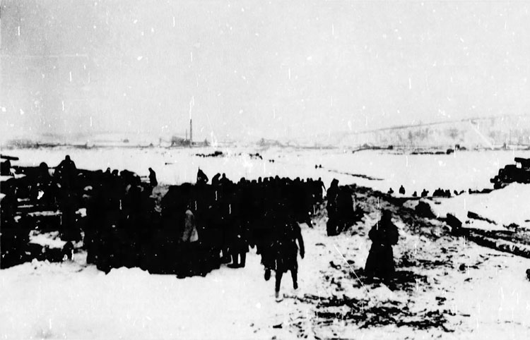
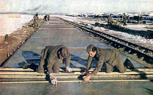
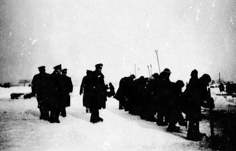
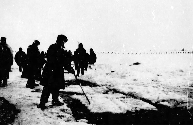
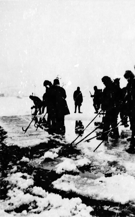
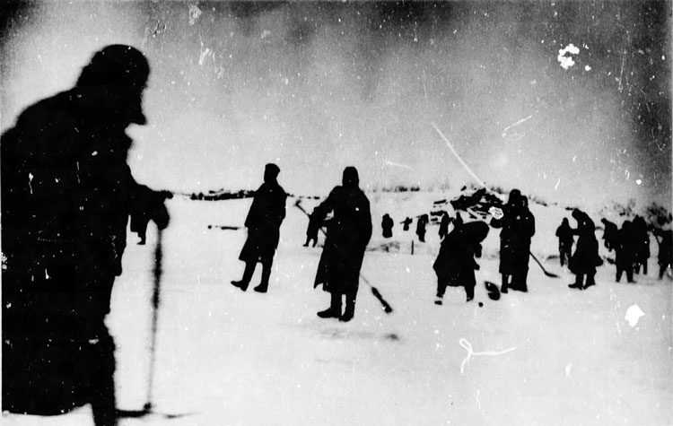
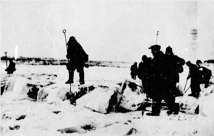
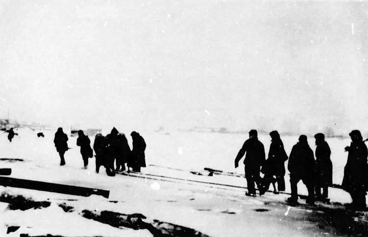
Photograph No. 1. (Marching to Work)
In order to keep the Ukrainian laborers on the job and to avoid any loss of time in transporting them to and from their camps at noon, they were fed at the bridge site by three field messes. Through the assistance of the local garrison headquarters and the Office of the District Commissioner extra rations were issued for Sunday work so that at least forty percent of the laborers also worked on that day.
To secure the transportation of these rations and of the construction equipment, fuel had to be made available. The procurement of gasoline became especially difficult since its normal issue at that time had been stopped.
Horses and sleds were required for the transportation of rails, sleepers and logs from distant depots and of the blocks of ice from pits located 200 meters away.
III. THE GEOGRAPHICAL DATA
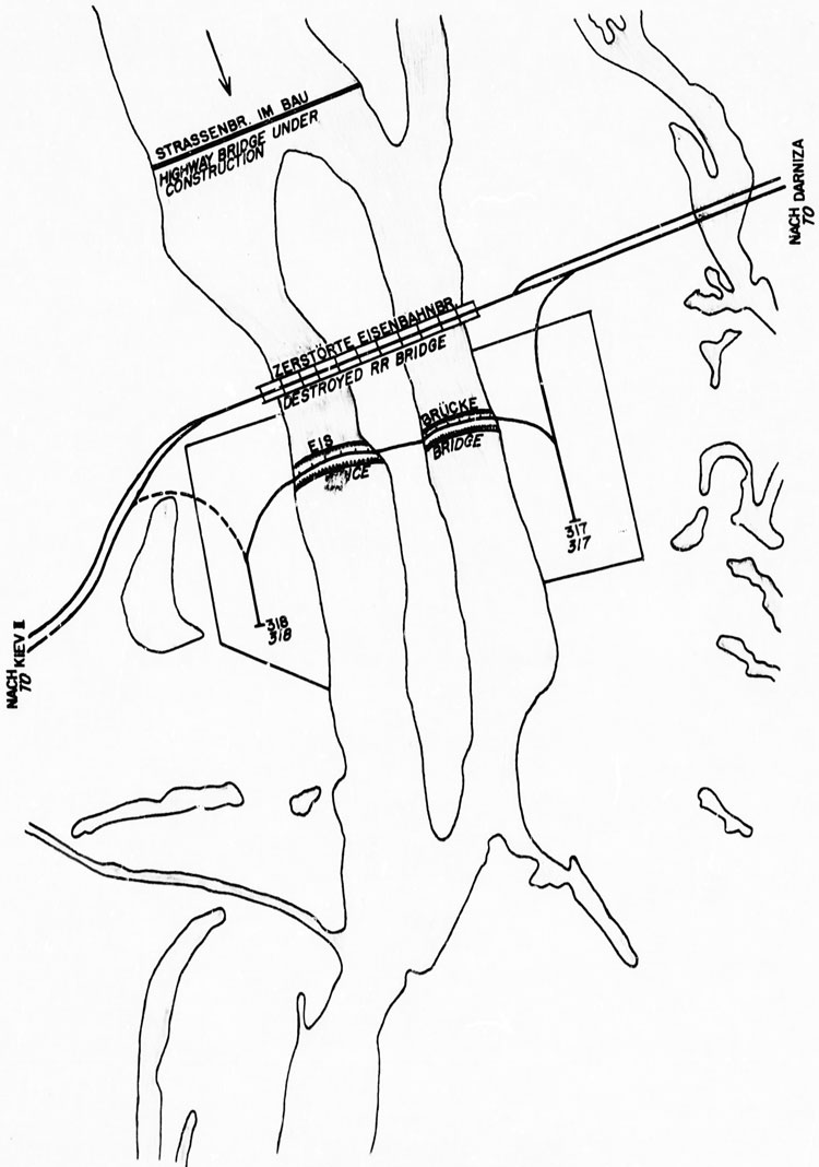
Sketch 1. Plan View of Ice Bridge отег the Dnieper
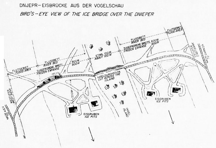
Sketch 2. Bird's-eye View of Ice Bridge
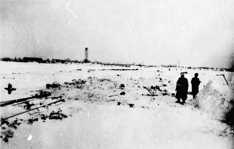
The ice railway bridge was located about 350 meters south of the destroyed southern railway bridge. On the military-geographic map of Kiev it is within map grid M 10.[*] At this point the Dnieper is 1,700 meters wide. There was a natural island in the middle of the river 150 meters wide which made it. possible to bridge the river with two spans. The western span was 800 meters in length and the eastern 700 meters. In order to avoid an elevation in the grade, a cut three and a half meters deep was made across the island.
[*] - The military-geographic map of Kiev is no longer available.
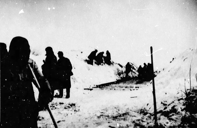
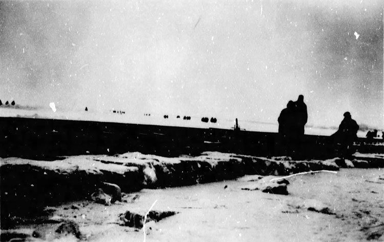
Photograph No. 2 (Cut Through the Island)
The western end of the track was connected, the spur to a lumber company, to the main rail line at a point between Freight Station II and the southern railway bridge. The eastern end was connected by a switch to the industrial spur of a sawmill located on the line from the southern railway bridge to Darniza.
From both banks of the river the ground rose gradually. The grade, however, was so slight that trains could be pulled up it by a single engine. The western end of the ice bridge was located within the grounds of a door-and-sash factory, and the eastern end within the grounds of a sawmill) on the military-geographic map of Kiev both are shown as individual entries and marked as numbers 317 and 318. Vehicle approaches to the ice bridge led through the respective factory grounds.
During the construction period, until 25 January, the average temperature was minus 29 degrees Centigrade (minus 22 degrees Fahrenheit). Later it rose considerably to minus 12 degrees Centigrade (9 degrees Fahrenheit), accompanied by a heavy snowfall which considerably hampered the progress of the work. The snow had to be removed from the frozen river surface as well as from the ice blocks already in place because the melting snow would not freeze hard enough to fuse the ice blocks and the superstructure into a compact mass. On 30 January the temperature again fell to minus 25 degrees Centigrade (minus 13 degrees Fahrenheit) enabling the construction to be accelerated.
IV. THE PLANNING
Initially it was planned to build a dam reinforced by steel hawsers which were to be anchored to each bank. Experiments, however, revealed that the hawsers would shift out of line or sag in the course of time and endanger the execution of the plan.
Since no one possessed any experience in ice bridge construction and since no mathematical data were available, determination of an adequate carrying capacity was calculated on the basis of the laws of physics dealing with "the buoyancy and carrying capacity of ice" and "the pressure of water."
CHAPTER 2. THE CONSTRUCTION WORK
I. THE EMBANKMENT
1. Construction of an Ice Block Layer, The frozen surface of the river was reinforced by a layer of ice blocks about fifty centimeters high and about twelve meters wide. For this purpose it was necessary to remove the snow completely in order to insure that the ice surfaces would freeze together.
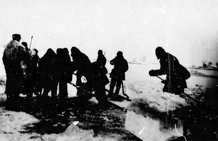
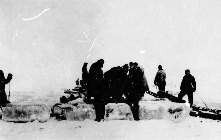
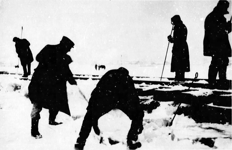
Photograph No. 3 (Loosening of the Ice Blocks)
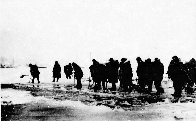
Photograph No. 4 (Loosening of the Ice Blocks)
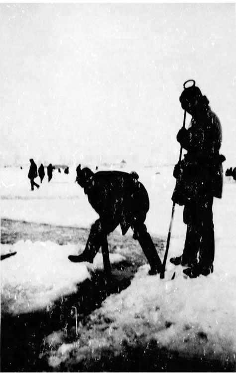
Photograph No. 5 (Cutting up the Ice)
Photograph No. 6 (Loosening Ice Blocks)
In supplying this ice block layer and also throughout the entire construction the strong current of the Dnieper, which approximately corresponds to that of the upper Rhine, was taken into consideration; the layer was built in the form of a curve facing upstream to prevent the ice blocks from being pushed downstream.
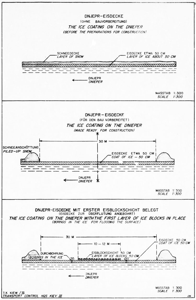
Sketch 3. Ice Coating on Dnieper Before Construction. Sketch 4. Ice Coating Prepared for Construction. Sketch 5. Ice Coating with First Layer of Ice Blocks in Place).
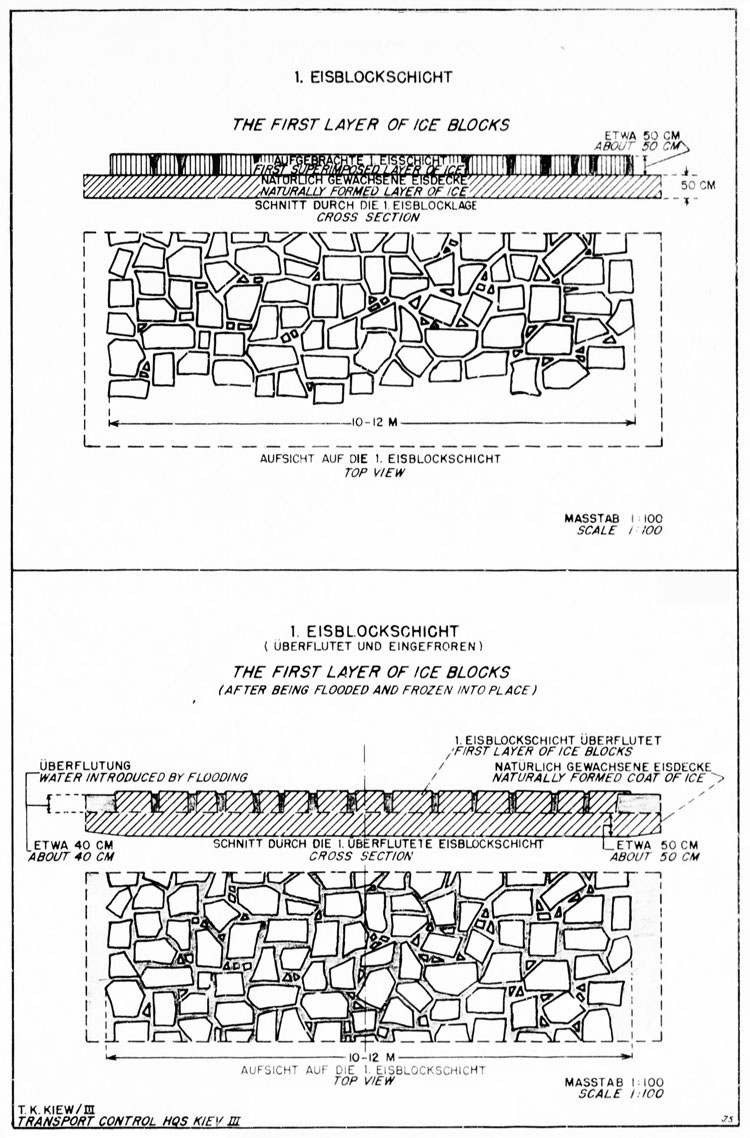
Sketch 6. First Layer of Ice Blocks. Sketch 7. First Layer After Flooding.
Ice Blocks measuring 45-55 by 40-60 by 40-80 centimeters were used to construct the additional layer, and interstices were filled with smaller lumps of ice. Skilled cutters obtained the ice blocks from pits located 200 meters downstream» from where the blocks were transported on horse-drawn sleds to the building site. (See photographs 3-13).
Photograph No. 7 (Loosening Ice Blooks)

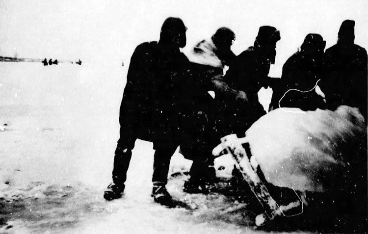
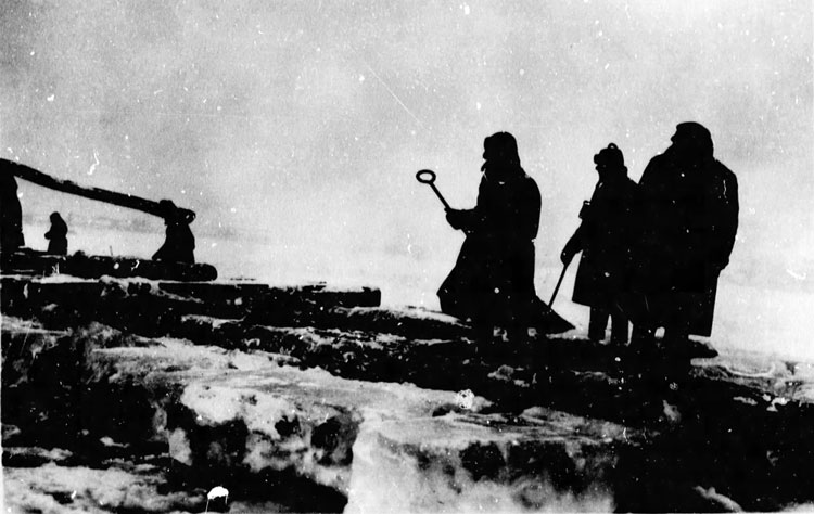
Photograph No. 8 (Pulling out the Blocks With Poles)
Photograph No. 9 (Pulling out the Blocks with Special Equipment)
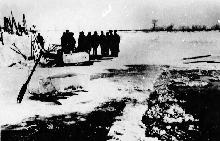
Photograph No. 10 (Ice Blocks Removed From the Pits)
Photograph No. 11 (Transporting the Ice on Sleds)
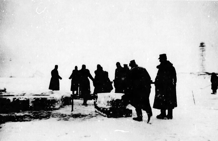
Photograph No. 12 (Cleaning off the Ice Surface)
Photograph No. 13 (Unloading the Ice Blocks)
2. Effects on the Existing Frozen Surface. The additional weight of the ice blocks upon the existing surface caused it to sag from ten to forty centimeters.
Since ice has only a low coefficient of elasticity, the frozen surface of the river cracked at points about fifteen meters, right and left of the center of the ice bridge. Water penetrated these cracks and to a certain extent flooded the first ice block layer. When this water froze it fused the first ice block layer to the surface costing of the river. (See sketches 7 and 8).
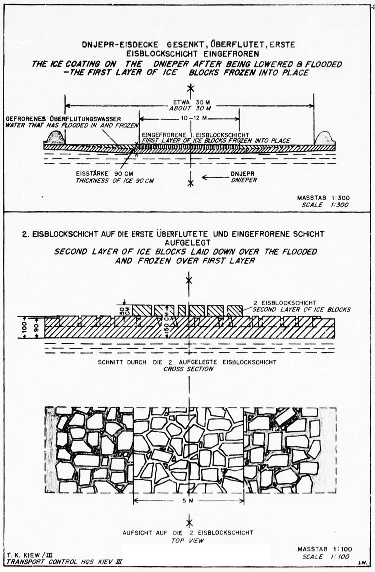
Sketch 8. Ice Coating on Dnieper With First Layer of Blocks Frozen Into Place. Sketch 9. Second Layer of Ice Blocks.
Flooding was further promoted by boring holes in the area under strain. (See Sketch No. 5, and Photograph No. 14)
Photograph No. 14 (The First layer of Ice Blocks)
3. Applying the Second Ice Block Layer. To further reinforce the layer already in place, a second ice block layer about fifty centimeters high and about five meters wide was laid and the interstices were likewise filled with lumps of ice. (See Sketches No's. 9, 10 and 11, and Photograph No„ 15)
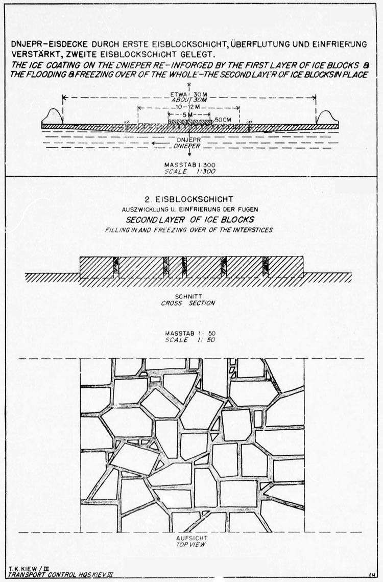
Sketch 10. Ice Coating Reinforced by First Layer. Second Layer in Place. Sketch 11. Second Layer. Filling in of Interstices.
Photograph No. 15 (With the First Layer of Ice Blocks Flooded and Frozen Into Place» the Second Layer is Being Laid)
4. Effects Upon the Entire Structure. The new ice layer caused the entire structure to sag an additional ten to thirty centimeters. Again a new flooding was accomplished by boring more holes since the existing holes had frozen solid after the fix of flooding. No more cracks and crevasses in the natural frozen surface of the river were observed. As a result of the additional flooding the entire structure was frozen into a compact mass of ice, and a bridge of adequate thickness and carrying capacity was completed. (See Sketches No's. 12. and 13).
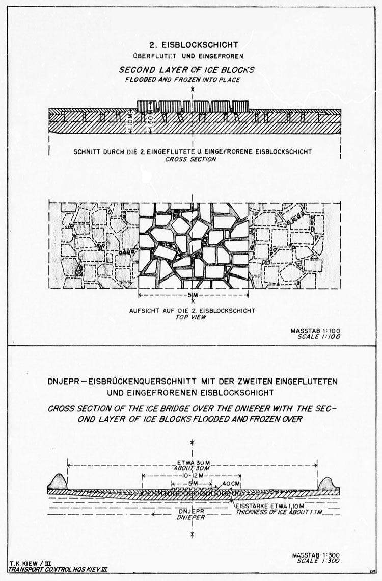
Sketch 12. Second Layer Frozen Into Place. Sketch 13. Cross Section of Ice Bridge With Second Layer Frozen Over.
II. THE SUPERSTRUCTURE
1. Preparing the Road Bed for the Rails. Upon the ice embankment two double rows of oak and pine logs with diameters of thirty-five centimeters and lengths of four to six meters were laid in staggered arrangement.
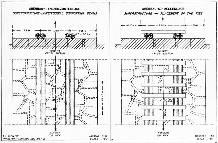
Sketch 14. Superstructure With Supporting Beams. Sketch 15. Superstructure, Placement of Ties.
Although the logs were not fastened together, they served to reinforce the ice bridge. The laying of the sleepers and rails completed the superstructure.
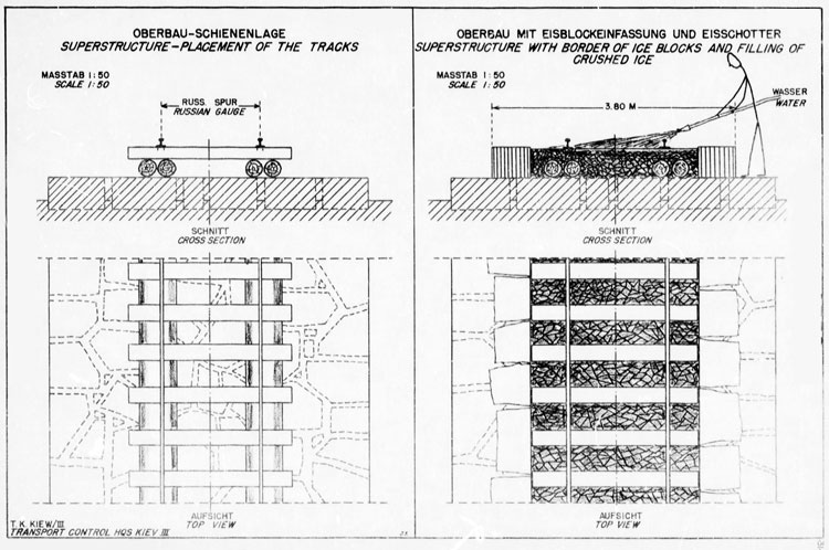
Sketch 16. Superstructure. Placement of Tracks. Sketch 17. Superstructure With Border of Ice Blocks and Filling of Crushed Ice.
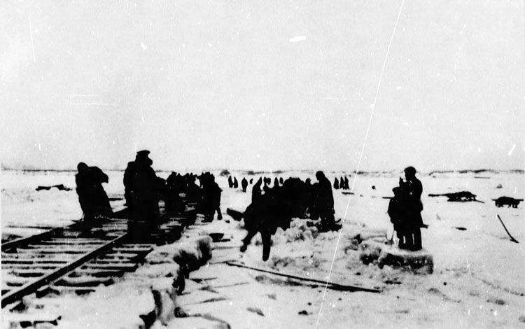
Photograph No. 16 (Beginning of the Superstructure)
Photograph No. 17 (Superstructure With Supporting Beams)
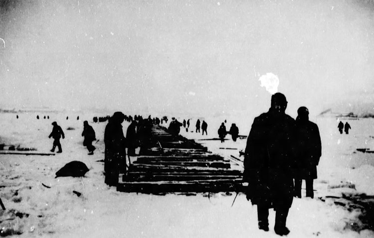
Photograph No. 18 (The Ties in Place Before the Laying of the Tracks)
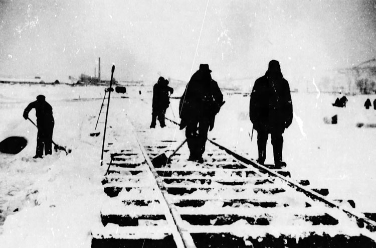
Photograph No. 19 (Transporting of Rails)
Photograph No. 20 (Superstructure Before Being Reinforced and Filled In)
2. Fixing the Superstructure Into Position. As mentioned above the logs had not been fastened down in any way. In order to hold them xn place a third layer of ice blocks was applied right and left of the superstructure and the interstices were filled with crushed ice level with the top of the sleepers. In order to combine the superstructure into a solid mass and to connect it firmly with the rest of the road bed, water was poured over the whole structure; as this froze the whole mass was consolidated into a single solid block of ice. (See Sketches No's. 13 and 14, and Photographs No's. 21-23)
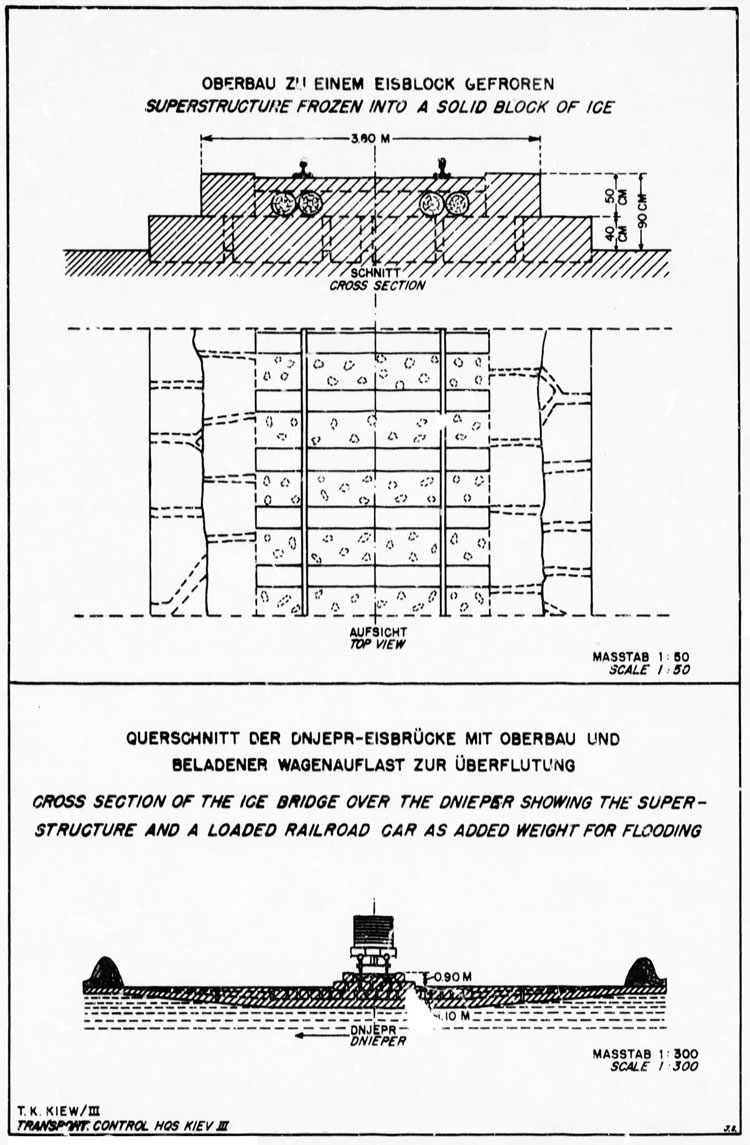
Sketch 18. Superstructure Frozen Into a Solid Block of Ice. Sketch 19. Cross Section of Bridge Showing Superstructure and Loaded Railroad Car as Added Weight for Flooding.
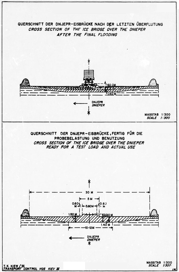
Sketch 20. Cross Section of Ice Bridge After Final Flooding). Sketch 21. Cross Section of Ice Bridge Ready for a Test Load.
Photograph No. 21 (Constructing the Border of Ice Blocks)
Photograph No. 22 (Superstructure with Reinforcing Ice Blocks)
Photograph No. 23 (Filling the Superstructure with Crushed Ice)
3. Total thickness of the Ice Bridge. A new flooding now increased the thickness of the ice bridge to a total of from 130 to 170 centimeters as measured from the top of the new surface to the underside of the original river ice.
III. THE APPROACHES TO THE ICE BRIDGE
Since the frozen river surface made it impossible to determine exactly where the flood line ended and the actual bed of the river began, the first ice block layer was extended to overlap the permanent river banks. The rise at these points was so gradual that it was unnecessary to construct any special coupling or swing joints in the railroad tracks. However, in case a serious depr3esion of the ice bridge was caused by heavy loads, the construction of swing joints at the approaches of the ice bridge was planned.
IV. REACTION OF THE ICE BRIDGE UNDER LOAD
When the ice bridge was tested with an engine and train weighing 120 tons the reaction was observed through a theodolite. Under the trial load the entire bridge structure was depressed forty-five centimeters, or about three and a half millimeters per ton. As the train moved off the bridge the entire structure raised itself twenty-six centimeters. The test indicated that no damage would result when the bridge was under stress and that the narrow limits of the elasticity of the ice were not being exceeded.
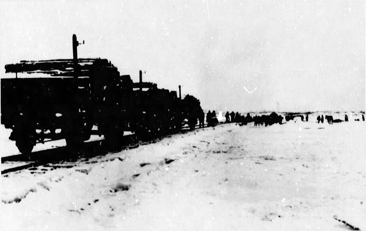
Photograph No. 24 (Weighing Down for the Final Immersion of the Bridge)
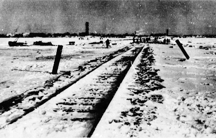
Photograph No. 25 (Completed Superstructure of the Ice Bridge Over the Dnieper)
V. CONSTRUCTION DATA
The time required for the construction was twelve days. The personnel employed in the construction of the ice bridge included engineers and technicians of the Kiev Army Construction Office, 360 German soldiers and 500-800 Ukrainian laborers.
On the island about 2,000 cubic meters of dirt v*re excavated by troops of the 88th Infantry Division.
Ice blocks totaling 15,640 cubic meters were cut, moved to the construction site, placed in layers and frozen into the bridge.
To establish a connection with the main railroad line leading to the destroyed southern railway bridge 1,600 meters of track were required.
For the road bed 6,200 meters of logs and 2,Лб5 sleepers were shipped to the bridge site and installed.
All together 13,500 cubic meters of snow were removed from the frozen river surface0 The working site was repeatedly cleared of several thousand cubic meters of newly fallen snow.
Approximately 3,750 cubic meters of water were sprinkled by pumps to facilitate the freezing of the entire structure including the railroad superstructure.
CHAPTER 3. ACHIEVEMENTS
Trains were able to pass over the bridge for about one month, from the beginning of February to the beginning of March when thawing weather set in. The use of the ice bridge would have been possible from the end of December, if the competent agencies had tackled the project earlier. The reduced thickness of the river ice at that time could have been compensated for by applying an additional layer of ice.
When it was no longer possible to use the bridge for railway traffic, only the rails were removed. The sleepers and beams that had been frozen into the ice were left on the bridge.
The capacity of the bridge was more than 4.500 wide-gauge cars per month.
It must be taken into consideration that, since switches had to be used on each bank of the river, a maximum of eight freight cars could be handled at one time. This slowed down the traffic considerably. The intention to build a through rail connection could not be realized because of terrain conditions. Once the ice bridge had frozen into a solid block, it could have carried far more than eight Russian freight cars.. A small-type engine was used for hauling.
The restricted amount of wide-gauge rolling stock prevented the bridge from being used to full capacity. The freight ears coming from the west could not be moved to the bridge due to excessive traffic elsewhere; and east of the Dnieper the cars were loaded with supplies. If the sequence of traffic had been normal, the capacity could have been doubled in spite of the limitations entailed by the use of switches.
The purposes for which the bridge was constructed, namely the transportation of the wide-gauge rolling stock across the Dnieper and the supply of the Sixth Army with sufficient reserve stocks, were fulfilled in spite of the various difficulties.
[P-152]