Slave to the Game
Online Gaming Community
ALL WORLD WARS
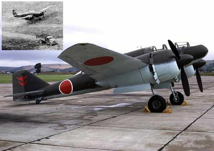
PHOTO INTERPRETER'S GUIDE TO JAPANESE MILITARY INSTALLATIONS
1945.
PART I. *
MILITARY INTELLIGENCE DIVISION
1 SEPTEMBER 1945
WAR DEPARTMENT
WASHINGTON, D.C.
NOTICE
This guide has been prepared to assist photo interpreters of the ground forces in the interpretation of Japanese military installations and materiel.
SECTION I. PHOTO INTERPRETATION
Specialized knowledge and guides are usually necessary to make identifications of enemy weapons, field equipment, and installations on air reconnaissance photographs. This publication, arranged as a guide for ground force interpreters, is intended primarily for men with the specialized knowledge requisite to derive maximum information from aerial photographs. Photographic examples are given of typical Japanese installations and materiel. In some cases, where adequate coverage of Japanese subjects was not available, photographs taken in the European theater are substituted. These will be found chiefly in the earlier sections which deal with manifestations of military activity common to all war areas. Vehicle tracks, for example, speak the same language in Asia as in Europe,
In presenting the information on Japanese weapons and vehicles, actual ground photographs of captured equipment are given first, whenever possible. To facilitate comparison, the vertical ground photographs were taken with the camera fixed, so that the scale is constant. The scale of the vertical views of small weapons is approximately 1:20; the scale of the verticals of the wheeled pieces and vehicles is approximately 1:25. Exceptions are the vertical views of the Type 96 150-mm howitzer (approximately 1:30) and the amphibious tank (approximately 1:40).
Where available, photographs are also included of weapons found in actual installations, followed by stereo-pairs and obliques. Supplements will be issued in the future to give information and photographs not now available. Blank spaces are left for insertion of photographs acquired by individual interpreters.
Photographic interpreters are aware that objects, large and prominent when observed at close range on the ground, are reduced in scale and importance when viewed among a multitude of objects within the scope of an aerial photograph. Definite conclusions can be drawn from certain features which are visible on photo-gyaphs and are invariably associated with specific types of equipment. But to reach these conclusions the interpreter not only must know the methods of reading photographs, but he must also be familiar with the enemy's equipment, organization, and tactics.
The trained interpreter will use aerial photographs for many purposes. To aid movements of our own forces, photographs can be used to supplement small-scale or inaccurate maps in the selection of cross-country routes and road circuits, bridge sites, or river crossings. Also, photographs have an important use in aerial survey and for interpretations required by the air forces. But these subjects, as well as the technical problems involved in taking, developing, and printing photographs, are not considered here, since they are discussed in other publications.
This publication deals only with the type of information required by army ground forces for intelligence purposes. This information concerns terrain, enemy order of battle, and enemy air and ground activity, in forward as well as rear areas. Information about the enemy to be gained from photographs includes location of field defenses, obstacles, artillery positions, headquarters, communication systems, supply routes, and reserves. Detection of camouflage also is possible and offers a major challenge to the skill of the interpreter.
Evaluation of enemy activities, as revealed in photographs of areas under his control, gives an indication of his offensive and defensive intentions. Indications of a planned offensive include a sudden increase in the number of artillery positions and of other military installations, such as advanced landing fields for small planes, light railways and roads, and field hospitals. An imminent offensive also may be disclosed by an increase in the number and size of ammunition and supply dumps, concentrations of rolling stock in railroad stations, and the construction of new trenches at the front lines.
Defensive preparations likewise will be revealed on aerial photographs. New lines of barbed wire, with occasional trenches and dugouts in the rear, mark the placement of a new defensive line. Old trenches may be deepened or otherwise strengthened, and repairs and additions made to wire entanglements. Behind the front lines, defensive or withdrawal preparations will be indicated by removal of light railways, by increased traffic on roads and railways toward the rear, and by rearward disposition of artillery positions.
Many more sources of intelligence are available concerning the position of the enemy in the forward area than of his dispositions in his lines-of-communication and base areas. Reports of forward troops, the information obtained from observation posts and patrols, and the results of interrogation of enemy prisoners and deserters can be collated and used to supplement or confirm information derived from interpretation of aerial photographs. This variety of intelligence sources should be utilized fully, for in the forward area the interpreter must attempt to locate such small installations as machine-gun posts, dugouts, observation posts, routes of patrols, and gaps in wire.
TECHNIQUES OF INTERPRETATION
The interpreter's tools are the stereoscope, maps, and photographs. His principal aids are stereoscopic vision, tones and shadows on photographs, and his own knowledge and trained imagination.
Analysis of aerial photographs is a process of visual perception that occurs in two stages. The first stage is the immediate recognition by the interpreter of objects that are familiar to him because of his training, experience, and background. The second is the interpretation of evidence that might lead to the discovery of additional objects, not at first apparent but suspected because of their normal relation to visible items.
Oblique photographs are comparatively easy to decipher, since they provide views familiar in normal every-day visual experience. To the interpreter every-day visual experience is a kind of library of memorized customary elevational views to be drawn upon for recognition of objects. In the interpretation of vertical aerial photographs, however, the interpreter cannot fall back upon his library of memorized visual images alone. He must deduce the identity of objects from the top views of them, which are likely to be completely unfamiliar to him.
Familiarity with the principles of stereoscopic photography and stereoscopic fusion is required for proper interpretation. Stereoscopic examination of photographs and a close study of tones and shadows are the means by which the existence of objects on photographs is visually determined. Shadows reveal form, size, relief, and often camouflage. Tones are gradations of black and white appearing on photographs because varying amounts of light are reflected by different surfaces. These tones indicate the nature, shape, and texture of objects.
The interpreter should realize the importance of reading photographs as he would a map, but in much greater detail. From a photograph and a knowledge of the average dimensions of ordinary objects, an imaginary reconstruction can be made of the landscape.
For example, in studying photographs of rural areas, the interpreter must keep in mind the customary appearance of farm buildings and the typical layout of farms in the country in which the military operations are taking place. He also must be familiar with the agricultural practices of the region in order to avoid errors in interpretation. Farm buildings and systems of cultivation in Southeast Asia or on islands of the Southwest Pacific may appear peculiar on photographs when viewed by men accustomed to the agriculture of the United States. The result may be an erroneous interpretation of military activity. Also, paths and tracks made by workers, vehicles, and animals on farms can be distinguished from tracks made by military activity by appearance, age, and apparent purpose.
The interpreter studies the terrain pictured on aerial photographs from the standpoint of military tactics. For example, the general layout of a defensive system can be determined by a study of the object defended and the relief of the terrain. The detailed layout of the elements of the defenses can be determined from apparent possibilities for fields of fire, communication facilities, and accommodations for troops. Further examination should be made for evidence of concentrations at logical positions for bivouac areas and supply dumps and for indications of military occupation along communication lines.
Finally, the interpreter should be familiar with camouflage methods and techniques for detecting camouflage and dummy installations on photographs. Camouflage is a highly important element of any defense and can be divided conveniently into two categories: camouflage against air observation and camouflage against ground observation.
| Weapon | Average number of guns (per battery) | Revetment size (inner diameter)(feet) | Average number of fire control revetments (per battery) | Type of mount | Approximate over-all length of weapon |
| 6.5 mm and 7.7-mm machine guns | No average | 6 to 8 | None | Tripod or bipod | 3 feet 7 inches |
| Type 95 (1935) 13.2-mm machine gun | 1 to 10 | 7 to 10 (single), 9 to 12 (twin) | None | Tripod | 6 feet |
| Type 98 (1938) 20-mm automatic cannon | 2 to 6 | 10 to 16 | 1 (small) | Pedestal, sled, or trailer | 7 feet |
| Type 96 (1936) 25-mm automatic cannon | 2 to 12 | 8 to 10 (single), 1o to 16 (twin), 10 to 16 (triple) | 1 or 2 (small) | Pedestal | 7 feet 6 inches |
| Vickers-type 40-mm automatic cannon | 2 | 10 to 16 | 2 (small) | Pedestal | 9 feet 5 inches |
| Type 88 (1928) 75-mm AA gun | 4 to 6 | 18 to 22 | 3 to 6 | Five outriggers | 11 feet 6 inches |
| Type 3 (1914) 76.2 dual-purpose gun | 3 | 14 to 20 | 2,3, or 4 | Pedestal | 10 feet 8 inches |
| 76.2-mm Naval gun | 2 | 16 (square) | 1 | Pedestal | 11 feet 3 inches |
| Type 98 (1938) 100-mm dual-purpose gun | 2 or more | (?) | (?) | Pedestal | 20 feet 7 inches |
| Type 14 (1925) 105-mm AA gun | 2, 4, or 6 | 23 to 25 | 3, 4, 5, or 6 | Six outriggers | 17 feet |
| 120-mm 40-caliber Naval gun | 4 | 20 | 2 | Pedestal | 16 feet 6 inches |
| Type 3 (1914) 120-mm Naval gun | 2 to 4 | 20 to 25 | 2 | Pedestal | 18 feet 4 inches |
| Type 10 (1921) 120-mm dual-purpose gun | 4 to 6 | 21 to 28 | 3, 4, or 5 | Pedestal | 18 feet 6 inches |
| Type 89 (1929) 127-mm dual-purpose gun | 2 (3 revetments) | 33 to 38 | 2 (building and finder) | Pedestal | 20 feet |
| Type 3 (1914) 140-mm naval gun | 2 or 3 | 34 to 37 | 1 or 2 | Pedestal | 24 feet (including shield) |
| 150-mm 40-caliber naval gun | 2 to 4 | 26 to 30 | 1 or 2 | Pedestal | 21 feet |
| Type 41 (1908) 150-mm 50-caliber Naval gun | 2 to 4 | 31 | 1 or 2 | Pedestal | 25 feet |
| Type 41 (1908) 150-mm 45-caliber Naval gun | 2 to 4 | (?) | 1 or 2 | Pedestal | (?) |
| 200-mm 45-caliber gun | 2 | 37 to 39 | 1 or 2 | Pedestal | 38 feet 10 inches |
| Type 3 (1943) 200-mm short Naval gun | 2 | 10 to 25 | 1 or 2 | Pedestal | 6 feet 8 inches |
| 240-mm howitzer | 4 | (?) | 1 or 2 | Pedestal | 12 feet 6 inches |
| 240-mm 26-caliber gun | 4 | (?) | 1 or 2 | Pedestal | 22 feet |
| 240-mm railway gun | 2 (?) | None | (?) | Railway | (?) |
| 280-mm howitzer | 4 | (?) | 1 or 2 | Pedestal | 17 feet 2 inches |
Identification aid chart for principal Japanese antiaircraft and coast defense guns.
SECTION II. TRACKS
Tracks provide one of the most valuable guides to the enemy's activity in forward areas, but because they are obvious, they are sometimes neglected. A variety of information can be derived from tracks visible on photographs, including roads in use, main communication trenches, the condition of trenches, location of forward dumps and bivouac areas, active artillery positions, location of headquarters, wire and gaps in wire, patrol paths, observation posts, advance listening- posts, artd occupied shell holes. The appearance of new tracks or the gradual disappearance of tracks will give positive or negative information of the enemy's activities.
In mobile warfare it is unlikely that tracks will be visible on photographs taken shortly after a new position has been occupied. However, if the position is occupied for more than a few hours, tracks made in the vicinity will give some indication of its location, as well as provide a basis for an interpretation of the type and amount of military activity.
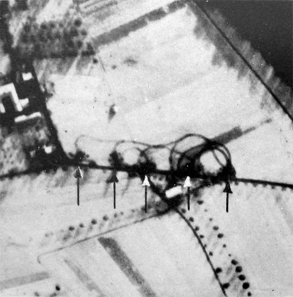
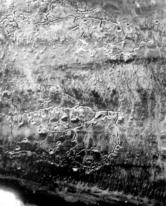
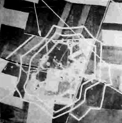
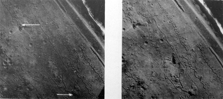
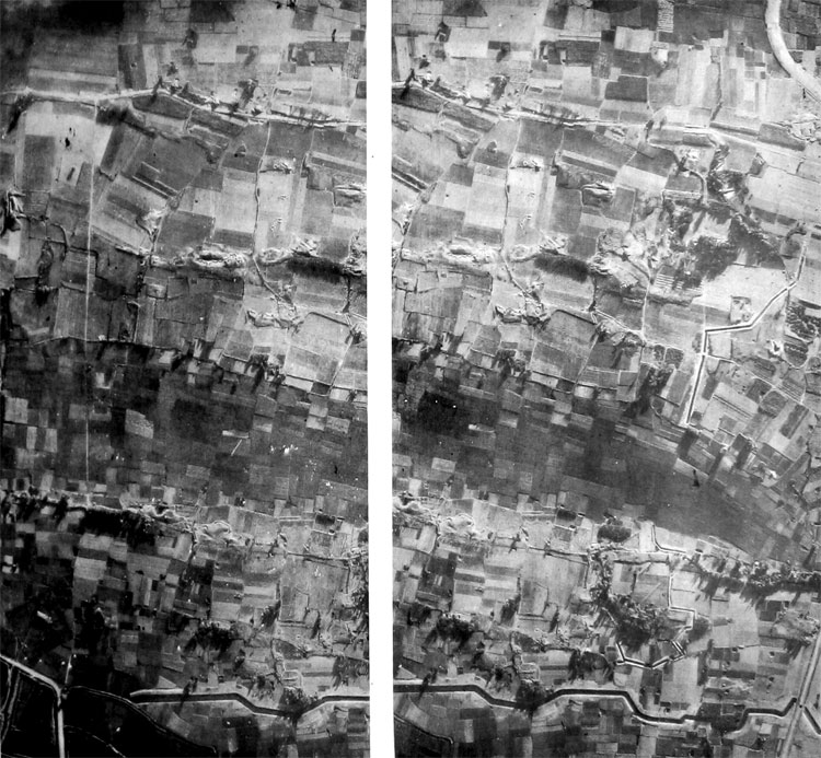
The road circuit and track activity shown ... confirm an interpretation of a possible supply area in the woods.
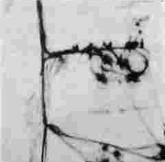
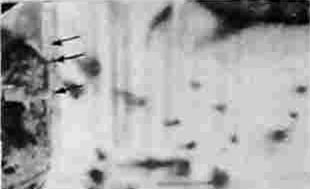
Four occupied gun positions are indicated by tracks. A fifth position is located approximately 250 yards from the main group. Three light antiaircraft guns have also been installed.
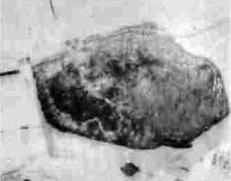
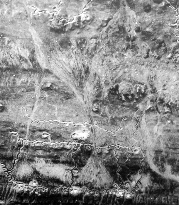
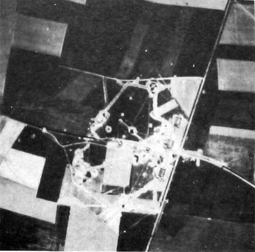
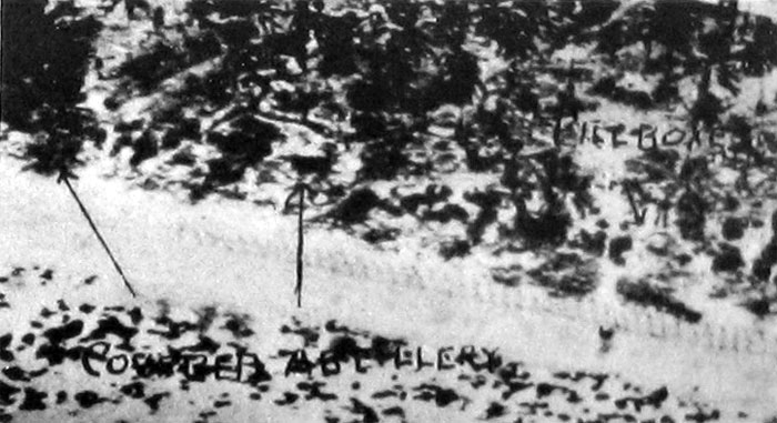
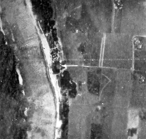
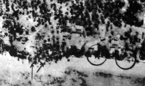
This single photograph illustrates how tracks reveal vehicular parking and military positions along the edge of wooded areas.
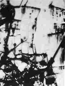
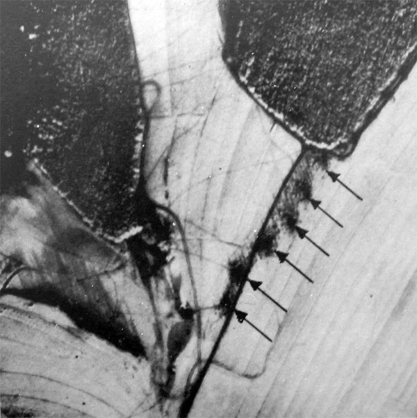
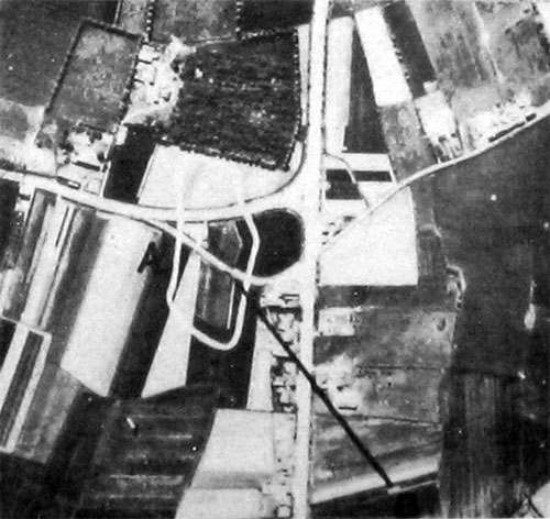
Tracks visible here indicate vehicles have pulled off the road.
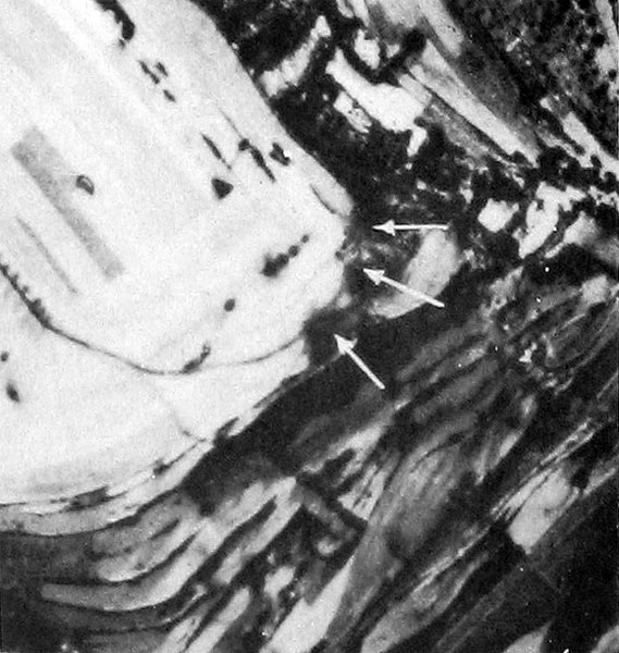
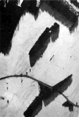
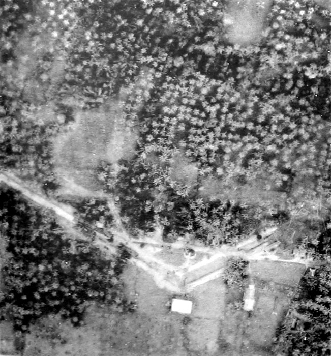
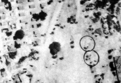
Two or possibly three medium field artillery guns are sited in the corner of an open field. Note the activity indicated by the tracks.
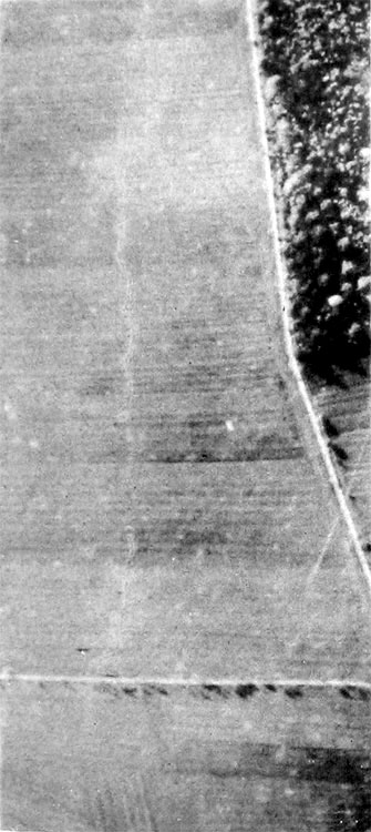
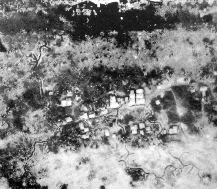
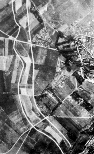
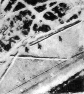
Three field artillery pieces have been located on a secondary road thus eliminating tracks.
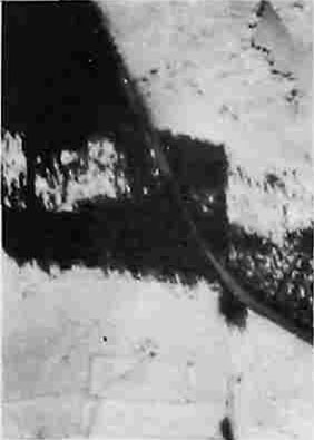
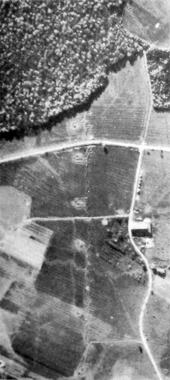
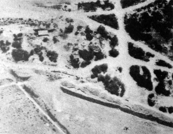
A four-gun battery has been placed along the secondary road at the edge of woods.
Five light field artillery guns.
Six light field artillery guns.
SECTION III. TRENCHES
Trenches are readily distinguished by their traversed or zigzag trace. The hastily dug defenses used in mobile warfare generally consist of separate weapon pits or slit trenches, each accommodating one or several men. If the enemy remains in the same position for several days, the slit trenches may be connected to form a continuous trench system. While this joining-up process is being accomplished, the enemy may resort to digging shallow communication trenches as temporary connecting links between the fully dug individual holes.
Oblique photographs taken from the rear of highly organized positions are often very valuable, since ground camouflage designed to obstruct frontal observation of the position will be seen from the rear and thus will no longer be an obstacle to interpretation. Details along the forward face of a trench, such as covered machine-gun emplacements and dugout entrances, are often revealed more clearly in oblique rear views than in any other type of photograph.
THE ENEMY DIGGING-IN
The division interpreter must be familiar with the characteristics of the enemy's ground defenses. He must make a continuous study of the enemy's progress in constructing the main line of resistance and must always be on the watch for development of any new line of resistance.
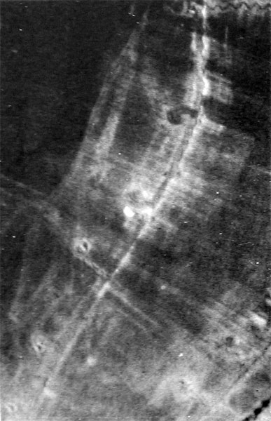
Connecting-up is underway here. The trench system between fox holes is only portiaily completed.
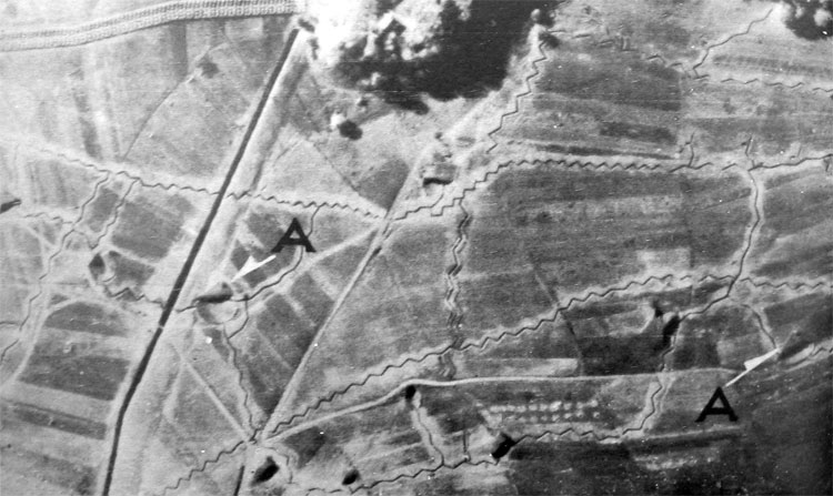
Fire trenches, communication trenches, machine-gun pits, and dugouts are visible.
Dugouts under construction.
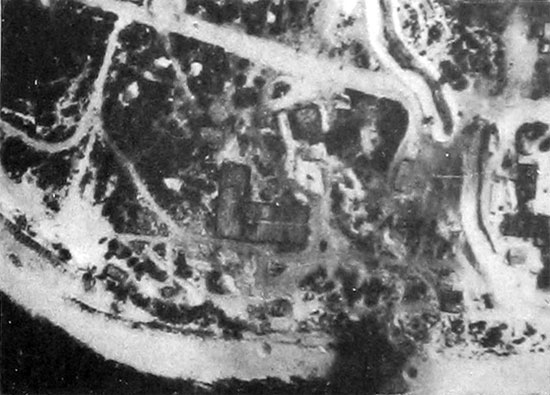
Development of an enemy strongpoint.
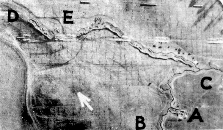
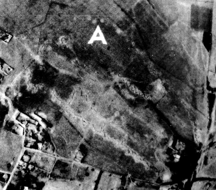
An Italian second-line Infantry position. Noted on the photographs are; (A) Incomplete dugout (B) smoothly graded soil, (C) to (D) incomplete trench, and (E) riflle and machine-gun pits.
German defenses, showing dragons' teeth, antitank ditch, pillboxes, casomates, and personnel shelters.
Japanese defenses on Iwo Jima, including fire trenches, machine-gun pits, mortar positions, and shelters. (1)
Japanese defenses on Iwo Jima, including fire trenches, machine-gun pits, mortar positions, and shelters. (2)
A Japanese antitank ditch
Japanese defensive position on Leyte Island, Philippines
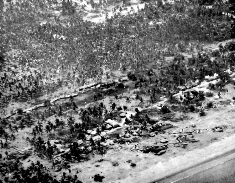
Oblique photograph of the area shown on the previous picture.
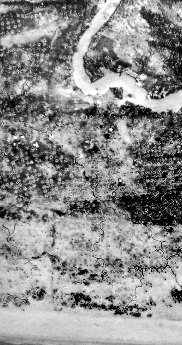
Japanese entrenchments on Leyte Island, Philippines.
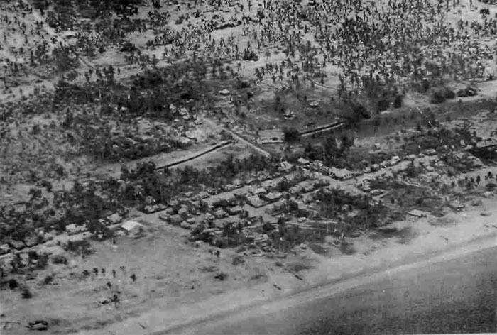
Oblique photograph of the area shown above. The Japanese defensive position includes fire trenches, communication trenches, heavy weapons pits, pillboxes, and antitank ditches.
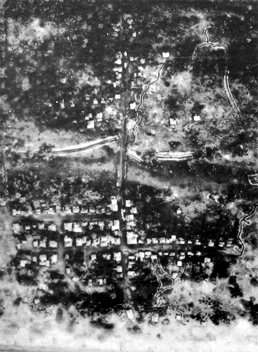
Japanese infantry defenses.
SECTION IV. WIRE AND MINEFIELDS
Discovering indications of wire and mines, surrounding an installation or as added protection for a strongpoint, presents a complex problem for the interpreter. However, a detailed and comparative study of the tones in a photograph will reveal differences in growth of vegetation between the lines of protecting wire. It should not be concluded that no wire exists because there are no signs of it on a vertical photograph. An oblique photograph may reveal wire not visible on a vertical. The presence of wire may be betrayed by tracks on either side of it or by paths which suddenly change direction in passing through the entanglement- Wire should be suspected in connection with all trench systems and along natural features such as streams, canals, and high ground which are natural defensive positions; around defended posts and shell holes; occasionally around forward battery positions; in hedges, ditches, and sunken roads; and around fortified villages or buildings.
The presence of mines will be difficult to detect, but they should be suspected in conjunction with wire entanglements- Japanese minefields do not always follow a definite pattern, and sometimes an accidental or deliberate detonation will be the first indication of a mine belt.
Wired-in mine belt as a perimeter defense for a radar installation. (1)
Wired-in mine belt as a perimeter defense for a radar installation. (2)
(A) suspected antivehicular minefield, and (B) suspected antitank gun. Comparative study with on earlier photograph of this area or with photos showing known local agricultural activity will establish whether this is actually a minefield or is merely agricultural activity.
Crosscountry mine belt. The tone of the photograph above will often assist in the detection of a mine belt. Note the footpaths along the edges of the wire enclosing the mine belt
ANTITANK MINES
Mines provide a cheap method of passive defense against tanks. Where our units are known to have tanks, the Japanese consider the laying of antitank mines as the most essential duty of the division engineer officer. The mines are placed in a conventional manner covering the logical routes of tank approach. Bridges in defensive areas are habitually mined, and any bridge which has been in Japanese hands must be carefully examined for the presence of contact mines before a tank unit is allowed to cross.
Japanese tank barricades have all possible detours heavily mined, and it is common Japanese practice to lay a few mines under temporary barricades with the idea that if attacking forces remove the barricade, mines laid underneath it will not be suspected.
Unless antitank mines are buried and carefully covered they can generally be seen on a large-scale aerial photograph. If the mines are buried, the photographic interpreter will rarely discover any evidence of them, although he should be alert for spoil, paths, or vehicle tracks that may appear parallel to rows of mines.
Mines near water's edge on Mille Island.
Mines on Marcus Island.
SECTION V. DEMOLITIONS AND OBSTACLES
Before a withdrawal the enemy may prepare bridges, roads, and road junctions for demolition, and as this preparation forms a good indication of his intentions, it is important to note it as early as possible. Such preparation often takes the form of small excavations made at the scene of a proposed demolition. These can be seen on large-scale photographs as little black dots, varying in number and surrounded by disturbed earth.
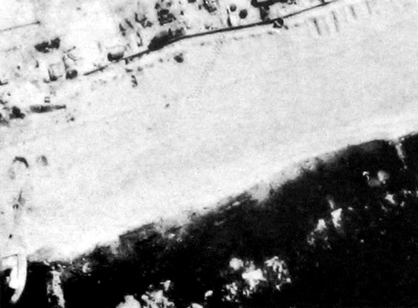
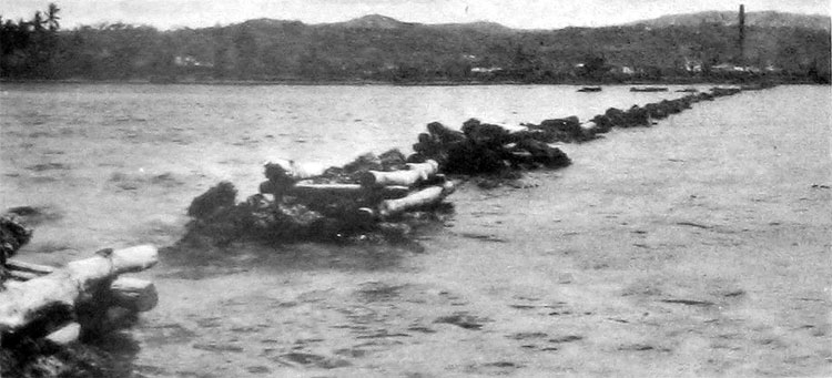
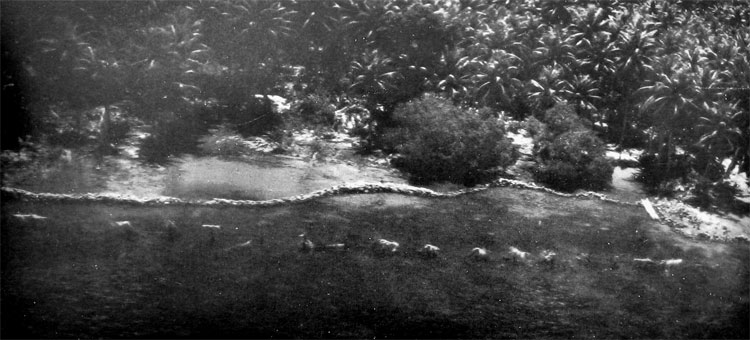
Obstacles are widely used and are numerous in type. They may be laid on main roads leading to the enemy-occupied area, in open fields to curtail air-landing operations, or along beaches to hinder amphibious operations. In ground operations, crossroads, defiles, causeways, bridges, deep road cuts, and side-hill road cuts, as well as adjacent fields, should be examined on photographs for possible obstacles or road blocks. When photographed at low tide, types of beach obstacles and their weaknesses may be discovered. It should be remembered that wire entanglements are used frequently in connection with obstacles of all types. Types of obstacles include fixed concrete road blocks, movable road blocks, wire barriers, debris, prepared anti-air-landing obstacles, ditches, dragons' teeth and rail obstacles, anti-beach-landing preparations, walls, and arrangements of natural materials.
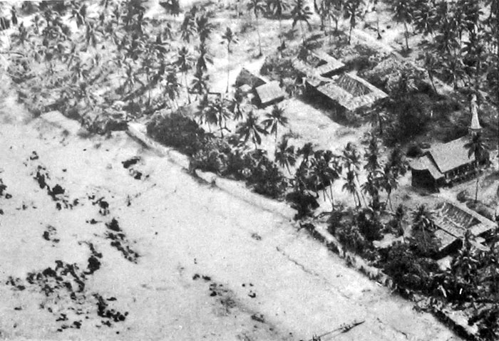
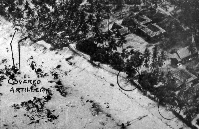
Japanese beach obstacles. (1)
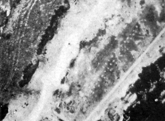
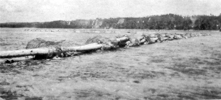
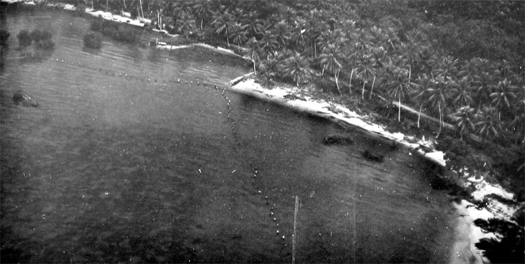
Japanese beach obstacles. (2)
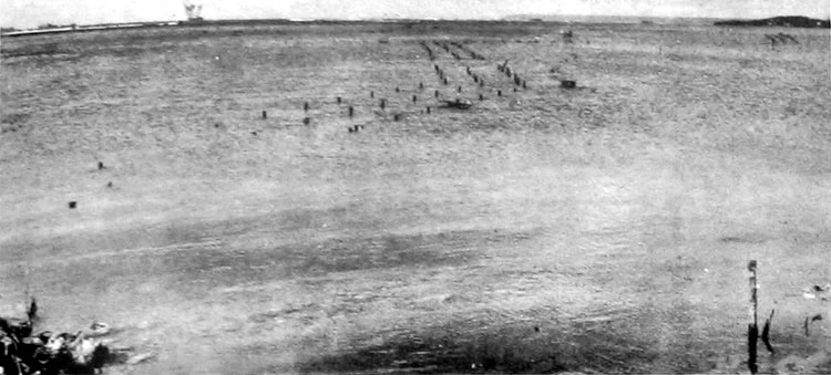
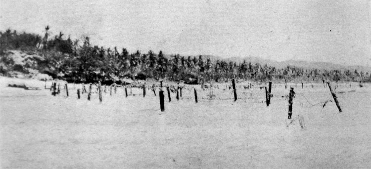
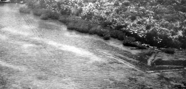
Japanese beach obstacles. (3)
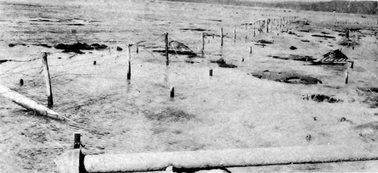
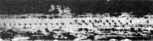
Japanese beach obstacles. (4)
Japanese beach obstacles. (5)
Japanese beach obstacles. (6)
Japanese beach obstacles. (7)
Japanese beach obstacles. (8)
Japanese beach obstacles. (9)
Oblique photograph of Japanese antl-beach-landlng obstacles on Luzon Island, Philipplnes.
Japanese obstacles placed along the beaches of Luzon.
Other types of Japanese obstacles placed along the beaches of Luzon. Note the arrowhead-shaped fish trap.
SECTION VI. PILLBOXES AND CONCRETE STRUCTURES
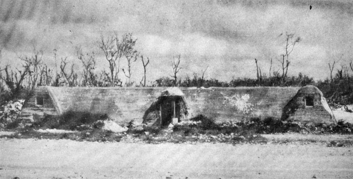
Concrete has played an increasingly important part in modern defensive warfare. Concrete forts are a common feature in all static lines, while smaller pillboxes are to be found in the defense of coast lines, towns, and villages, and nearly all vulnerable points. Concrete fortifications are nearly always carefully camouflaged and may not be apparent on photographs until after the area has been cleared by shell fire.
Japanese pillboxes may be classified in six groups, derived from the material used in construction. The six classifications, illustrated in the photographs that follow, include pillboxes made of coconut logs, coral rocks, combination of coconut logs and coral rocks, concrete, metal, and miscellaneous materials.
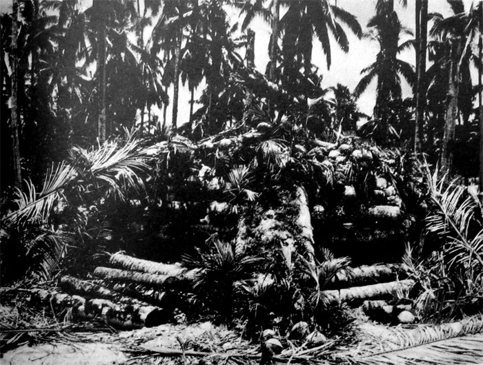
Coconut-log pillbox.
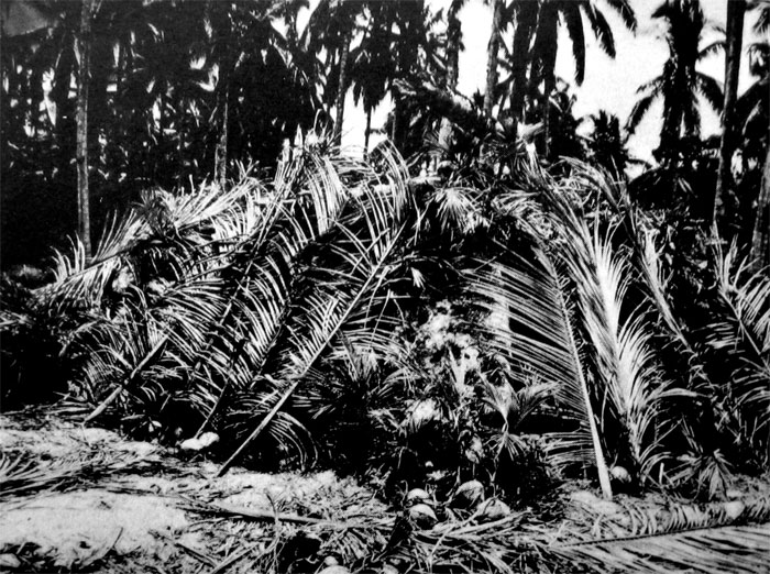
The same pillbox camouflaged.
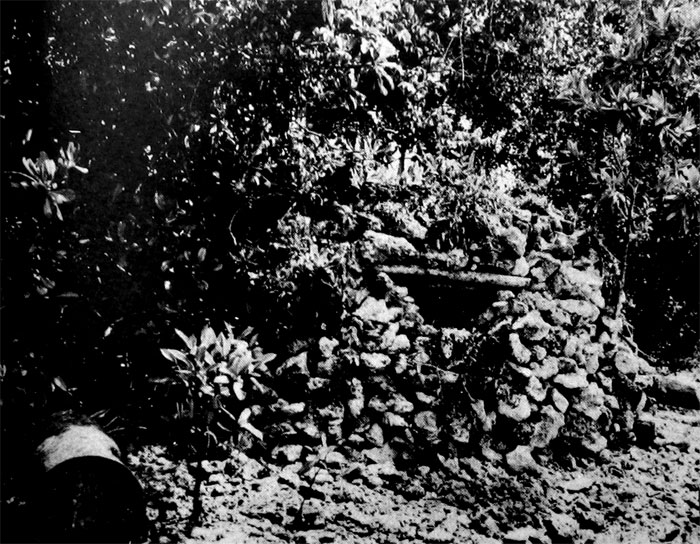
Coral-rock pillbox.
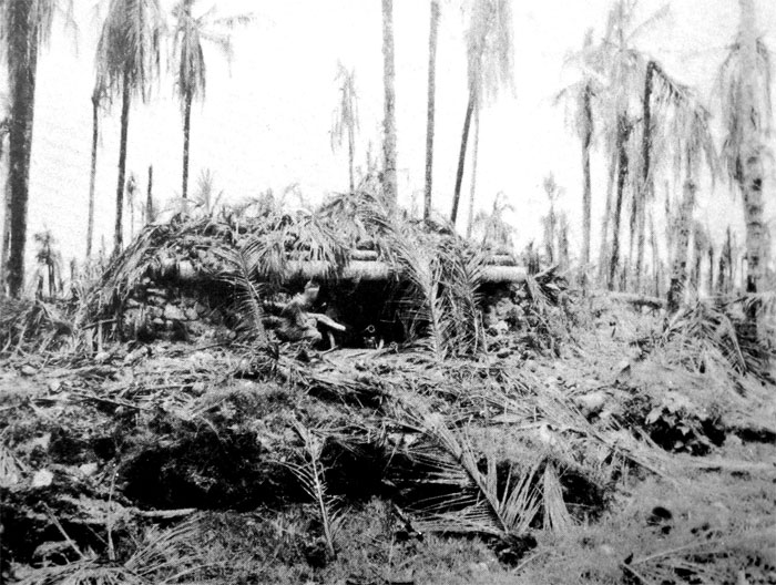
Combination coconut-log and coral-rock pillbox.
Shelter.
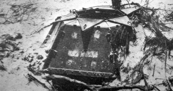
Metal pillbox.
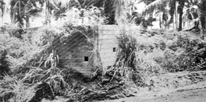
Concrete pillbox.
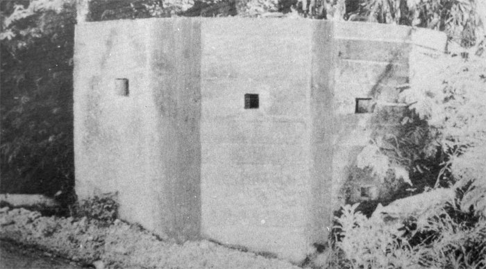
Concrete pillbox.
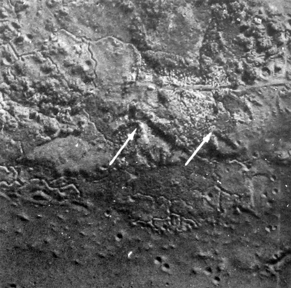
Scale 1:6,650, Iwo Jima. Two camouflaged pillboxes, identified by the cutaway bank affording a field of fire.
Oblique of concrete German-type blockhouse built by Japanese on Saipan lsland.
Scale 1 -.6,650, Iwo Jima, Two casemates parallel to the beach with fire bays opening on
the flanks. Indicating probable use for antitank weapons.
Scale 1:10,000, Saipan. German-type blockhouse.
Pillboxes.
Pillboxes.
Casemate or blockhouse
Casemate or blockhouse
Blockhouse.
Camouflaged artillery positions and pillboxes.
Camouflaged artillery positions and pillboxes.
Pillboxes.
Pillboxes
Pillboxes.
Pillboxes. (1)
Pillboxes [same picture with annotation AWW]. (2)
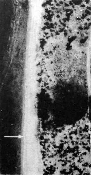
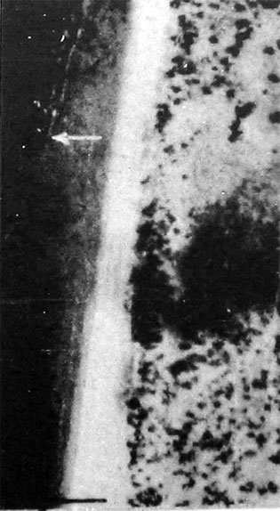
SECTION VII. OBSERVATION POSTS
Observation posts should be expected on commanding ground or at the end of isolated trenches leading to houses or to any prominent natural terrain feature. Tracks leading to such features also may indicate their use as observation posts. Wherever a trail or path ends, an especially careful examination should be made for an observation post. Cable trenches may connect observation posts to artillery positions.
Listening posts generally appear on photographs as small excavations in front of or actually in the wire which protects a defended position, and are connected by tracks to the position. If a field of fire can be obtained from the listening post, a machine gun may be placed there as well.
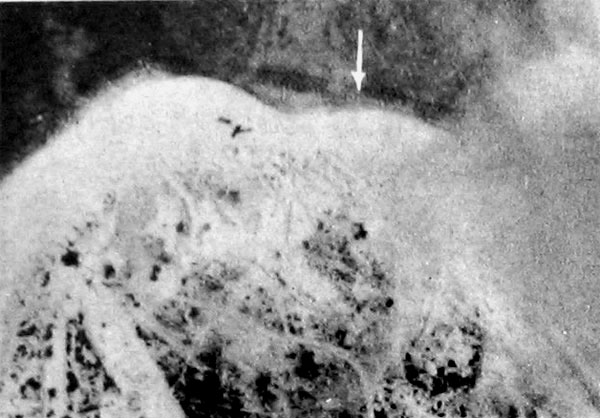
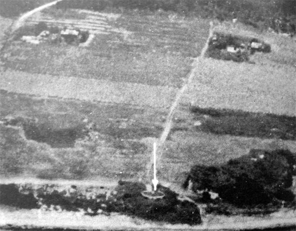
When high terrain features are not available, the Japanese locate observation posts on wood or steel towers or in trees. The low altitude oblique and stereo-pair on the next page show an example of a tree observation post that can be located on the verticals.
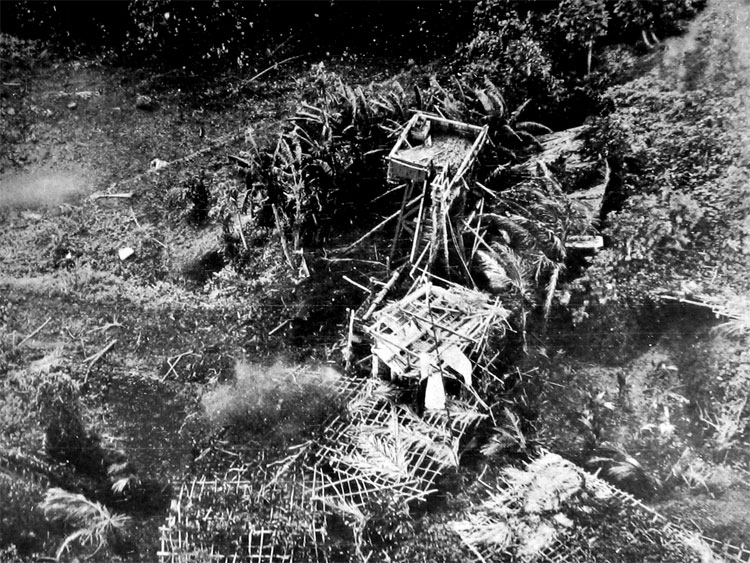
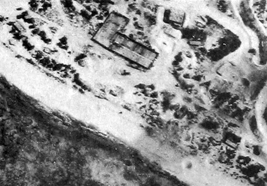
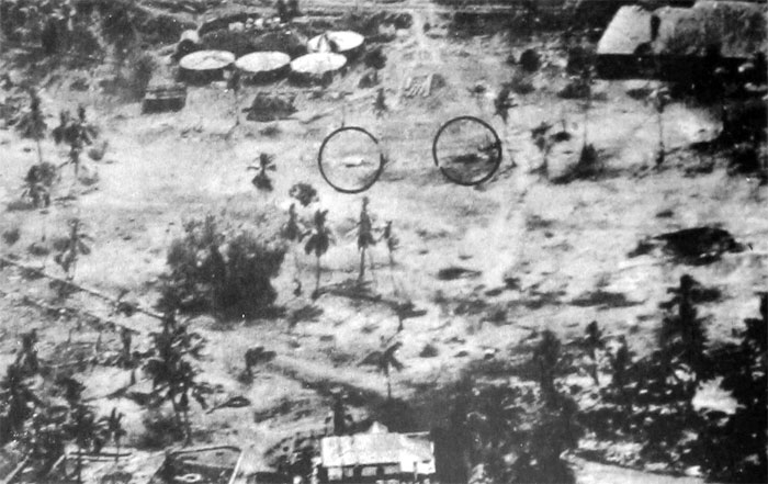
Japanese observation post and probable fire direction center on Ponape Island. Note the range finder.
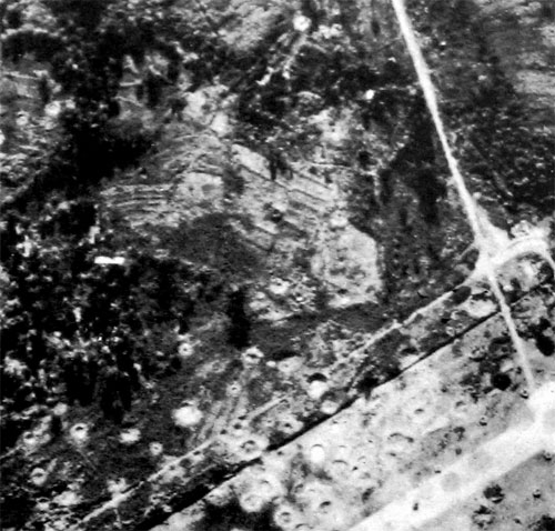
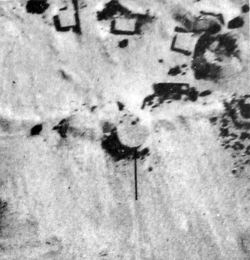
Scale 1:9,341, Mapanget, Celebes, Japanese observation tower.
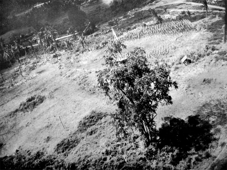
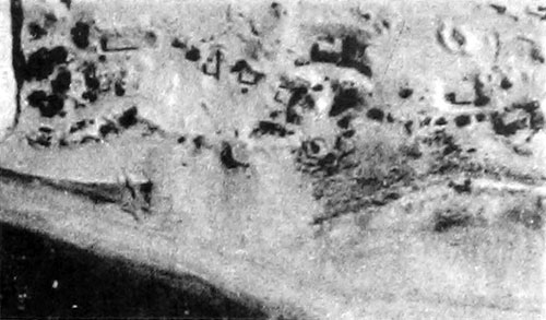
7-lnch focal length at minimum altitude, Maponget, Celebes. Oblique photograph of the observation tower shown in the stereo-pair above.
SECTION VIII. MACHINE GUNS
When machine guns are used in a highly developed defensive system, fixed emplacements are usually constructed for the guns, generally located close to the trenches. The Japanese frequently place their machine guns in covered and heavily camouflaged positions. Emplacements may be constructed in excess of the number of guns used. In very mobile warfare, emplacements are simpler and are often merely fox holes located in good natural cover.
Machine guns are extremely difficult to locate on photographs. As a rule they can be located only by knowing where to look for them. The ground should be studied very carefully and areas of a defensive system which offer good fields of fire as well as avenues of approach should be scrutinized. Machine-gun positions are normally located at these typical features: Where an angle occurs or where a traverse is constructed in a trench for flanking fire; at points within easy reach of a communication trench, with dugouts close by; in isolated positions where they may be recognized by a small forward gap leading to an emplacement and a protecting semicircle of wire; in excavations behind forward defenses.
Although the Japanese 6.5-mm and 7.7-mm heavy machine guns are primarily for use against ground targets, they are equipped with antiaircraft adapters. They are sometimes employed in a dual-purpose role along beaches or adjacent to the fire control equipment of an antiaircraft battery. Antiaircraft revetments for such guns are normally 6 to 8 feet in diameter.
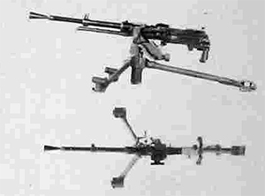
TYPE 11 (1922) 6.5-MM LIGHT MACHINE GUN (NAMBU)
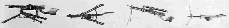
This is a gas-operated, hopper-fed, air-cooled machine gun. It is called the Nambu. The photographs on the left show the gun on its seldom-used tripod mount. The photographs on the Tight show its use with telescopic sight as a tank gun.
Characteristics
Length over-all ... 43.5 inches
Length of barrel ... 19 inches
Weight ... 22.5 pounds
Maximum range ... 3,800 yards
Cyclic rate of fire ... 500 rounds per minute
Revetments ... 5 to 10 feet in diameter
TYPE 96 (1936) 6.5-MM LIGHT MACHINE GUN
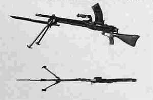
This is a gas-operated, magazine-fed, air-cooled, full automatic light machine gun.
Characteristics
Length over-all ... 41.5 inches
Length of barrel ... 21.75 inches
Maximum range ... 3,800 yards
Cyclic rate of fire ... 550 rounds per minute
TYPE 99 (1939) 7.7-MM LIGHT MACHINE GUN
This gas-operated, magazine-fed, air-cooled weapon is almost identical with Type 96.
Characteristics
Length over-all ... 42 inches
Length of barrel ... 21.5 inches
Maximum range ... 3800 yards
Cyclic rate of fire ... 800 rounds per minute
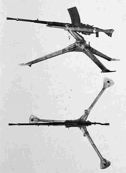
TYPE 92 (1932) 7.7-MM HEAVY MACHINE GUN
This gun may be equipped with an antiaircraft adapter which allows it to be elevated to an angle of 80 degrees.
Characteristics
Length over-all ... 45.5 inches
Length of barrel ... 29.5 inches
Maximum range ... 4,580 yards
Traverse ... 360 degrees
Elevation ... 11 degrees
Type of mount ... Pedestal or tripod
Revetment: Size ... 6 to 8 feet; Shape ... Square or circular
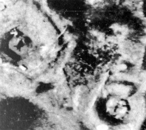
Low altitude oblique of Type 92 (1932) 7.7-mm heavy machine gun.
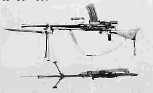
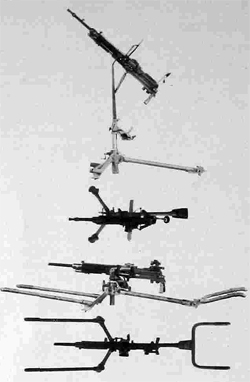
TYPE 92 (1932) 7.7-MM LEWIS-TYPE MACHINE GUN
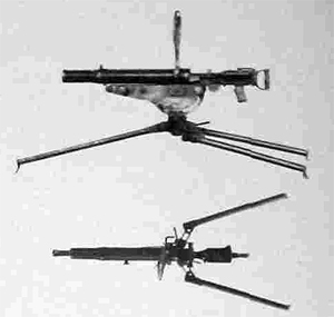
This weapon is an air-cooled, gas-operated, drum-fed, full automatic gun. It is practically a duplicate of the British Lewis. The cradle of the tripod can be moved from the horizontal to a vertical position, making a satisfactory aniaircraft mount.
Characteristics
Length overall ... 43.5 inches (approximately)
LTraverse ... 360 degrees
Elevation (with mount in AA position) ... 85 degrees
Cyclic rate of fire ... 550 rounds per minute
TYPE 1 (1941) 7.7-MM HEAVY MACHINE GUN
This is the new and lighter Japanese heavy machine gun. Its total weight with tripod is only 70 pounds, compared with the 129 pounds of the complete Type 92.
Characteristics
Length overall ... 42.4 inches (with flash hider)
Length of barrel ... 23.2 inches
Feed ... 30-round strip
Maximum range ... 3,800 yards
Cyclic rate of fire ... 550 rounds per minute
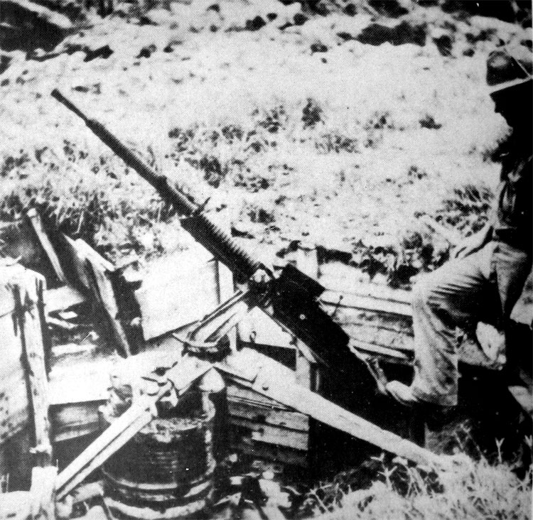
TYPE 93 (1933) 13.2-MM MACHINE GUN
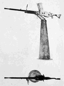
This Navy gun was designed primarily as an antiaircraft weapon but may be used against ground targets. It is air cooled and gas operated.
Characteristics
Length of barrel ... 56.5 inches
Maximum horizontal range ... 5,500 yards
Estimated maximum effective slant range 3,000 feet
Elevation ... 0 to 85 degrees
Traverse ... 360 degrees
Type of mount ... Pedestal or tripod
Revetment: Size ... 8 to 10 feet (single-barrel gun);
10 to 12 feet (double-barrel gun).
Shape ... Square, circular, hexagonal, or irregular.
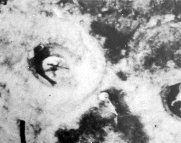
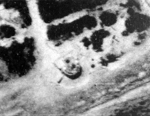
Low altitude oblique of 13,2-mm machine gun on tripod mount.
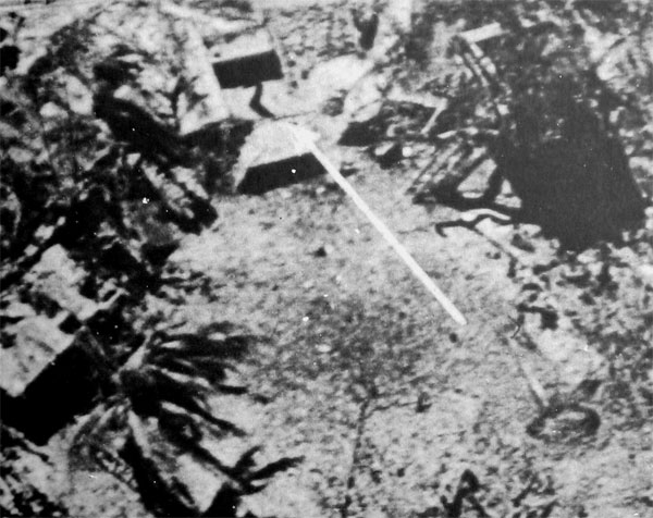
Pedestal mount for 13.2-mm machine gun in square revetment.
There is no gun on the mount.
Single-mount machine gun at Namur.
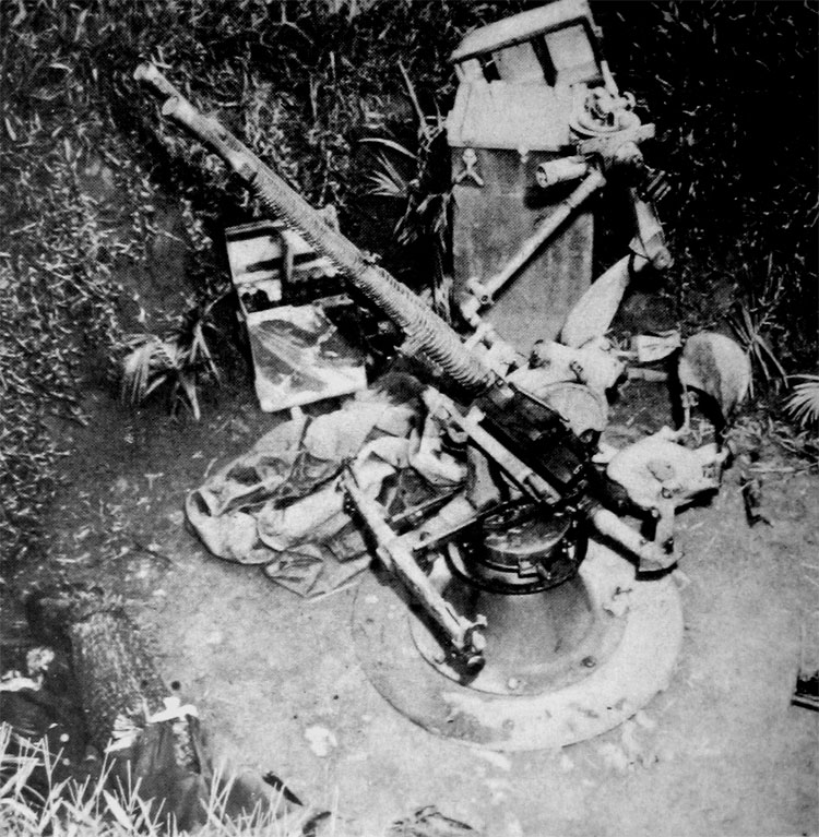
13.2-mm twin-mount machine gun on a pedestal at Kolombangara.
Twin-mount machine gun at Kolombangara. Note the double-wal revetment.
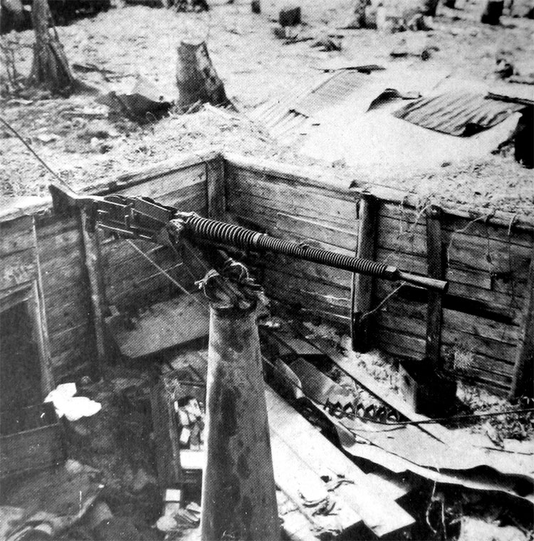
13.2-mm machine gun with tripod and mounted on barrels within the revetment.
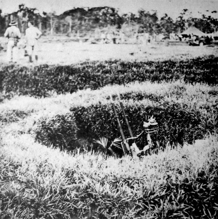
Twin-mount 13.2-mm machine gun captured at Kiska.
Machine guns and heavy weapons covering an antitank difch on Formosa, A thorough analysis of the photographs must be mode to determine the angle of fire for eoch probable weapon.
SECTION IX. MORTARS AND GRENADE DISCHARGES
Heavy mortar emplacements in large-scale defensive positions are sometimes casemated and are more conspicuous than machine-gun and antitank-gun positions because of the comparatively large emplacements they use. However, the smaller grenade discharger and small and medium mortar positions can be easily concealed from aerial observation. It is only by close cooperation with ground observers that these mortar positions can be definitely located. The interpreter will find it valuable to remember that the Japanese usually employ their mortars cither in pairs or as a battery of four weapons. Mortar positions are usually located behind front-line infantrymen and wherever possible in defiladed positions. Lines of approach constitute major targets for defensively emplaced mortars as well as for machine guns.
TYPE 98 (1938) 50-MM MORTAR
This is a smooth-bore, muzzle-loaded mortar with fixed elevation of approximately 40 degrees and a limited traverse.
Characteristics
Length of tube ... 25.6 inches
Total weight (with base) ... 50 pounds
Maximum range...
455 yards (with stick bomb);
320 yards (with bangalore torpedo)
Traverse ... 7 degrees
Weight of stick bomb fired ... 14.1 pounds
Fuse ... Time
TYPE 11 (1922) 70-MM MORTAR
This is an obsolescent muzzle-loaded rifled-bore mortar.
Characteristics
Total weight (including base plate) ...
133.75 pounds
Maximum range ... 1,635 yards (HE)
Elevation ... 37 to 77 degrees
Traverse ... 23 degrees
70-MM BARRAGE MORTAR
This is a smooth-bore, muzzle-loaded weapon of very simple construction. It fires a shell designed for use against low-flying aircraft. After reaching a height of approximately 1,700 feet, the projectile expels parachute-supported, high-explosive charges which are detonated in the air if struck by aircraft.
Characteristics
Length over-all ...75 inches (approximately)
Length of tube ... 48 inches
TYPE 97 (1937) 81-MM MORTAR
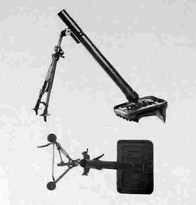
This weapon is almost identical with the U, S. 81-mm Mortar M1.
Characteristics
Caliber ... 82 mm
Length of tube ... 45.7 inches
Total weight ... 145 pounds
Maximum range ... 3,060 yards
Weight of shell ... 7.37 pounds
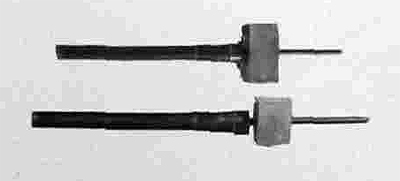
TYPE 99 (1939) 81-MM MORTAR
Type 99 has a much shorter barrel than Type 97 and is equipped for trigger firing with a mechanism at base of the barrel This weapon is fired by hitting the protruding end of the firing pin camshaft with a wooden mallet.
Characteristics
Length of bore ... 21.5 inches
Total weight ... 50,8 pounds
Maximum range ... 2,200 yards
Traverse ... 7 degrees
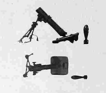
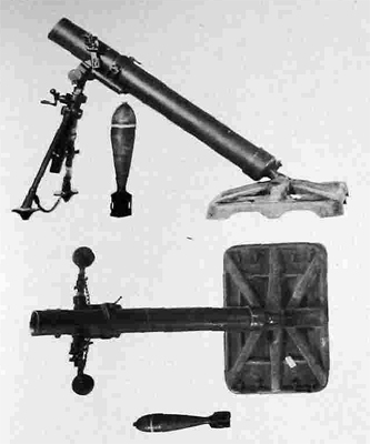
TYPE 94 (1934) 90-MM MORTAR
This is a smooth-bore, muzzle-loaded weapon. A special feature is the recoil system with two cylinders, one located on each side of the barrel.
Characteristics
Length of tube ... 48 inches
Total weight ... 353 pounds
Maximum range ... 4150 yards
Traverse ... 10 degrees
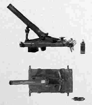
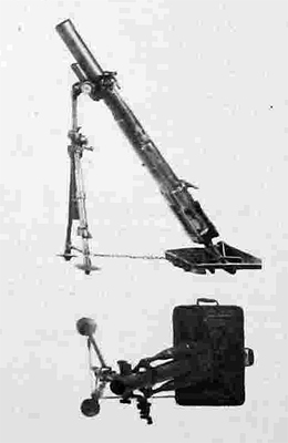
TYPE 97 (1937) 150-MM MORTAR
This weapon is a smooth-bore, muzzle-loaded mortar of conventional Stokes-Brandt-type design. It employs the same bipod as the Type 2 (1942) 120-mm mortar, which it closely re-sembles. The chief point of difference between the two weapons lies in the Type 2 120-mm mortar's often having the bipod attached near the middle of the tube, rather than at the muzzle.
Characteristics
Length of tube ... 75.37 inches
Total weight ... 770 pounds
Maximum range ... 4,650 yards
(with short HE shell)
TYPE 10 (1921) 50-MM GRENADE DISCHARGER
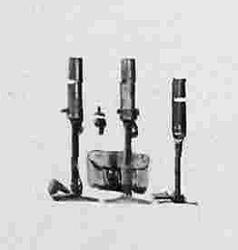
This is a smooth-bore, muzzle-loaded weapon.
It is used primarily for discharging pyrotechnics,
Characteristics
Length over-all ... 20 inches
Length of tube ... 9.5 inches
Weight ... 5.5 pounds
Range ... 250 yards
(with Type 91 grenade)
Rate of fire ... 20 rounds per minute
TYPE 89 (1929) 50-MM GRENADE DISCHARGER
This is a muzzle-loaded, rifled weapon which is widely used in the Japanese Army.
Characteristics
Length over-all ... 24 inches
Length of tube ... 10 inches
Weight ... 10.25 pounds
Range 131 to 711 yards
(with Type 89 shell);
44 to 208 yards
(with Type 91 grenade)
Rate of fire ... 20 rounds per minute
SECTION X. ANTITANK GUNS
Antitank guns normally will be sited to cover tank obstacles. They may be placed singly and, as they are small, may be extremely difficult to identify on small-scale photographs. As with machine guns, a thorough understanding of the characteristics and typical emplacements of the enemy's antitank weapons will be the interpreter's greatest aid. It should be borne in mind that light and heavy antiaircraft guns are frequently used in dual antiaircraft and antitank roles. In addition the Japanese have been known to use their field pieces, particularly 75-mm guns, in an antitank role.
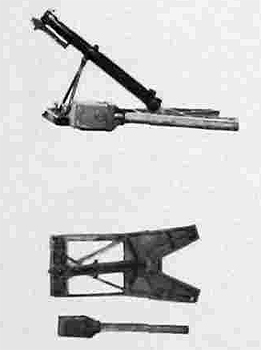
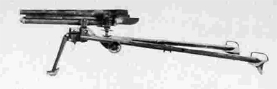
TYPE 97 (1937) 20-MM ANTITANK RIFLE
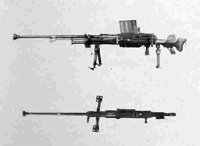
This is a semiautomatic, gas-operated, antitank weapon. Infantry can maneuver it in any terrain. Two men can carry it and it is easy to hide because of its low silhouette.
Characteristics
Length (without handles) ... 82.5 inches
Weight ... Gun-120 pounds. With shield and
carrying handles, 150 pounds
Traverse (total) ... 90 degrees
Rate of fire
... 12 rounds per minute
(semiautomatic)
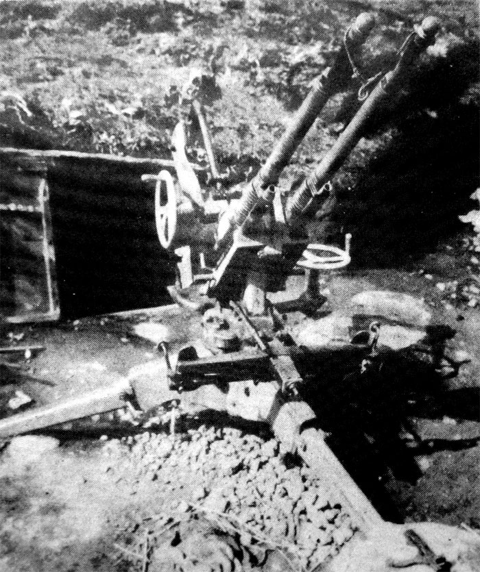
TYPE 98 (193B) 20-MM ANTIAIRCRAFT, ANTITANK AUTOMATIC CANNON
This is a gas-operated, full-automatic, all-purpose weapon, similar in mechanism to, but larger and heavier than the Type 97, 20-mm antitank rifle. The carnage permits firing from its wheels.
Characteristics
Weight ... 836 pounds (without wheels)
Maximum horizontal range ... 7,000 yards
Estimated maximum effective slant range ...
3,500 feet
Rate of fire ... 120 rounds per minute
Traverse ... 360 degrees
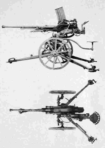
TYPE 11 (1922) 37-MM GUN
Although obsolete, and not primarily an antitank weapon, this gun is a valuable weapon for fighting in difficult terrain because of its light weight and low silhouette. Four men can carry this gun easily by inserting two hand spikes in recesses in front of the pintle.
Characteristics
Length (traveling position). ... 7 feet 6 inches
Length (firing position) 6 feet 11 inches
Height (firing position) ... 24 inches
Width of trail spread ... 4 feet 1.25 inches
Length of tube ... 36.5 inches
Weight ... 205.75 pounds
Traverse ... 33 degrees
Elevation ... -4.8 to +14 degrees
Ammunition ... APHE and HE
Typical emplacement ... Covered or shallow pit
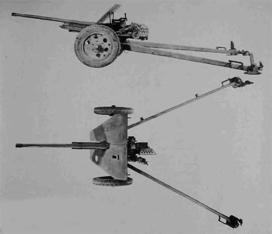
TYPE 94 (1934) 37-MM GUN
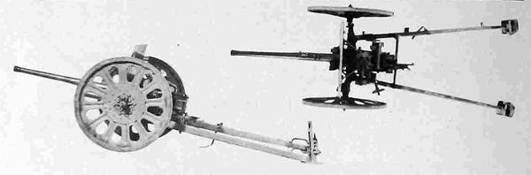
This is a close-support, flat-trajectory, single-shot weapon of the field-gun type. It is the organic weapon of infantry regiments.
Characteristics
Weight ... 710 pounds
Length (traveling position) . . . 12 feet 6 inches
Length (firing position) ... 9 feet 3 inches
Height (firing position) ... 3 feet 5 inches
Width of trail spread ... 8 feet
Length of barrel ... 5 feet 6.5 inches
Weight ... 710 pounds (with wooden
wheels) 812 pounds (with pressed
steel wheels)
Maximum range ... 5,000 yards
Traverse ... 60 degrees
Elevation ... —7 to +27 degrees
Ammunition ... APHE and HE
Typical emplacement ... Covered
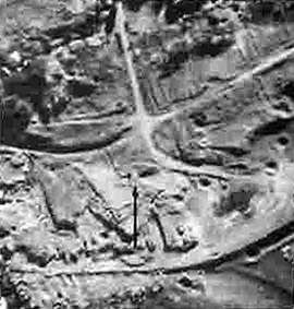
Scale 1:6,650. This photo, taken on Iwo Jlma, shows a
typical emplacement for the Type 94 37-mm gun. The cutaway portion of the bank for field of fire and the communication trench that leads into tho rear of the emplacement point out the location of the gun. This position was locatod for fire along the beach and the road that leads
into the interior.
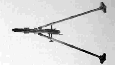
TYPE 1 (1941) 47-MM GUN
This is the only weapon specifically designated an antitank gun by the Japanese. Of modern design, it has a long barrel, reinforced at the muzzle, and is adapted for motor transport only.
Characteristics
Length of tube ... 8 feet 3.5 inches
Weight ... 1,660 pounds
Maximum range ... 8,400 yards
Traverse ... 60 degrees
Elevation ... -11 to +19 degrees
Ammunition ... APHE and HE
PART II. SECTION XI. ARTILLERY. SECTION XII. ANTI-AIRCRAFT ARTILLERY.
[*Note: During this online adaptation: a) Original was divided into 3 parts for faster webpage loading, there are no Parts I, II, II in the original; b) Second pictures in many stereo-pairs were not shown; c) Scales, indicated in the original edition don't corrwespond with the scales in online publication. d) If several pictures were grouped in the original under one annotation, in online edition annotation appears under each picture of the group with added numbers in round brackets. - AWW].